
Indoor automatic laser charging system and method

A charging system and charging method technology, applied in passive battery identification, data exchange chargers, current collectors, etc., can solve problems such as being susceptible to interference, low electromagnetic induction charging efficiency, and troublesome placement.

Active Publication Date: 2016-05-04
SHENZHEN BTL TECH
View PDF5 Cites 3 Cited by
  • Summary
  • Abstract
  • Description
  • Claims
  • Application Information

AI Technical Summary

Problems solved by technology

As people become more and more dependent on the benefits of these portable electronic devices, it is important to be able to use these devices at any time, but existing chargers for these electronic devices need to be charged Only by connecting with these electronic devices to be charged can charging be realized. On the one hand, when carrying the charger of the electronic device, the entanglement of the extended wire of the charger brings trouble to people; The length is limited, the charging range is limited, and the charging cable needs to be unplugged, which is very inconvenient to charge
[0003] Now there is a wireless charger, which uses the technology of electromagnetic induction charging, but the electromagnetic wave is divergent and is easily disturbed. The laser is unidirectional and not easily disturbed, so it is more conducive to the concentration of energy; and electromagnetic induction charging The efficiency is low and the range is short, generally only within a few centimeters, and there are troublesome placement problems; in addition, because electromagnetic waves are divergent, their radiation range is larger than that of lasers

Method used


Image

  • Indoor automatic laser charging system and method
  • Indoor automatic laser charging system and method
  • Indoor automatic laser charging system and method

Examples


Embodiment Construction

[0034] The present invention will be described in detail below in conjunction with the accompanying drawings and specific embodiments.

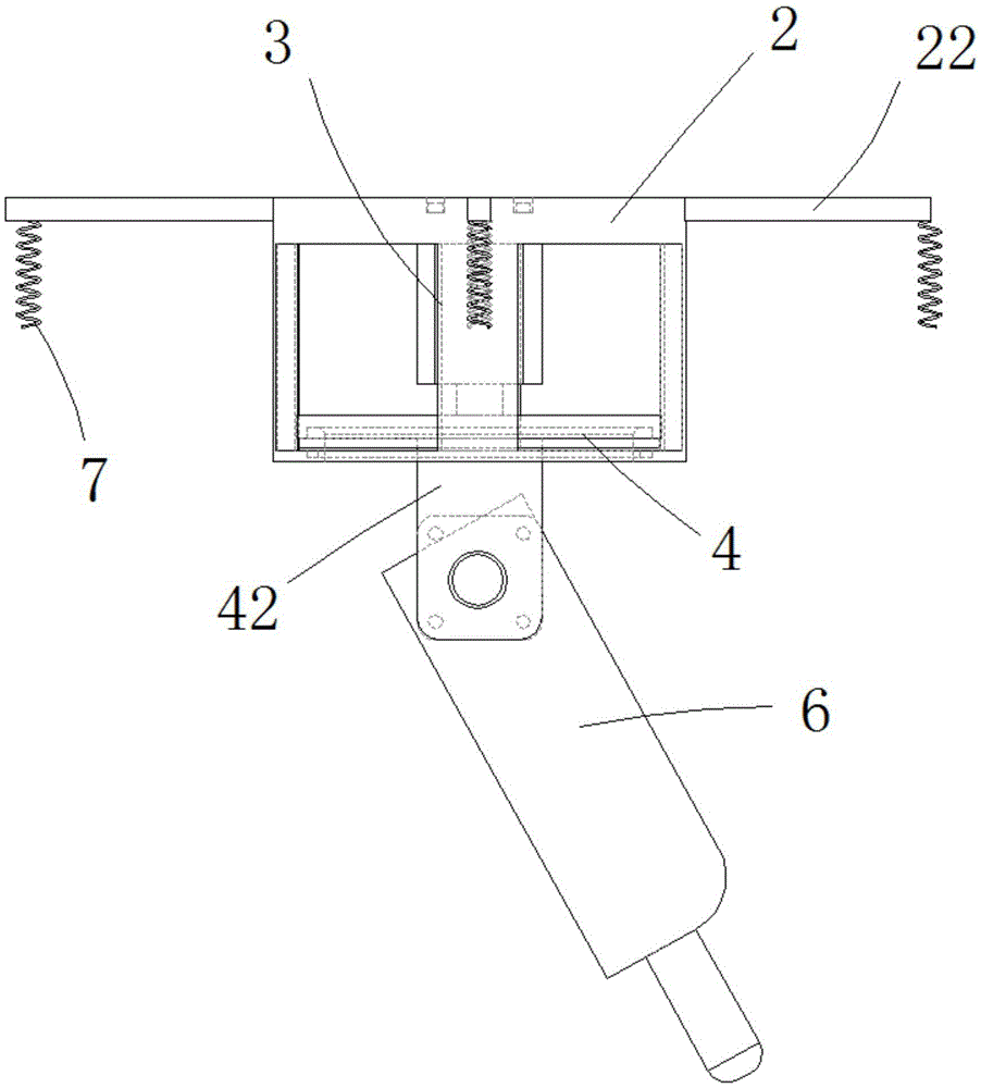
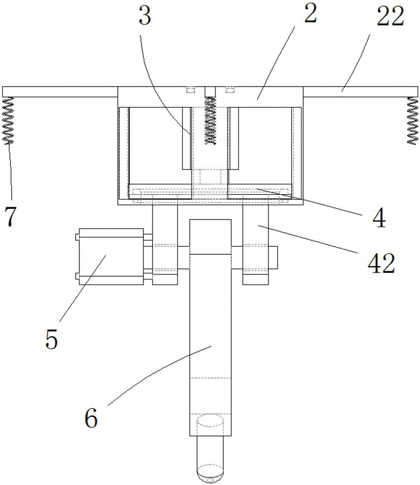
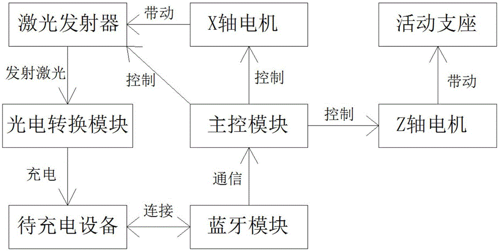
[0035] see Figure 1 to Figure 3 , the present invention provides an indoor automatic laser charging system, comprising: a fixed base 2, a Z-axis motor 3 mounted on the fixed base 2, an output shaft mounted on the fixed base 2 and connected to the Z-axis motor 3 The connected movable support 4, the X-axis motor 5 installed on the movable support 4, the laser emitter 6 installed on the movable support 4 and connected to the output shaft of the X-axis motor 5, and the drive circuit And several groups of bluetooth antennas 7 electrically connected with the driving circuit. The driving circuit includes a main control module and a bluetooth module electrically connected to the main control module, the bluetooth module is electrically connected to the plurality of bluetooth antennas, and the bluetooth module switches several bluetooth antennas und...


PUM


Abstract

The invention discloses an indoor automatic laser charging system and method. The indoor automatic laser charging system is characterized by comprising a fixed base, a Z-axis motor, a movable support, an X-axis motor, a laser emitter, a driving circuit and a plurality of groups of Bluetooth antennas, wherein the Z-axis motor is arranged on the fixed base, the movable support is arranged on the fixed base and connected with an output shaft of the Z-axis motor, the X-axis motor is arranged on the movable support, the laser emitter is arranged on the movable support and connected with an output shaft of the X-axis motor, the Bluetooth antennas are electrically connected with the driving circuit, the driving circuit comprises a master control module and a Bluetooth module, the Bluetooth module is electrically connected with the master control module and electrically connected with the plurality of Bluetooth antennas, the master control module is electrically connected with the X-axis motor, the Z-axis motor and the laser emitter respectively, the movable support rotates in a horizontal direction under the driving of the Z-axis motor, and the laser emitter rotates in a vertical direction under the driving of the X-axis motor.

Description

technical field [0001] The invention relates to a laser charging technology, in particular to an indoor automatic laser charging system and method. Background technique [0002] Portable electronic devices such as cell phones, digital cameras, notebook computers, and various other similar electronic devices provide users with great flexibility and convenience. As people become more and more dependent on the benefits of these portable electronic devices, it is important to be able to use these devices at any time, but existing chargers for these electronic devices need to be charged Only by connecting with these electronic devices to be charged can charging be realized. On the one hand, when carrying the charger of the electronic device, the entanglement of the extended wire of the charger brings trouble to people; The length is limited, the charging range is limited, and the charging cable needs to be unplugged, which is very inconvenient to charge. [0003] Now there is a...

Claims


Application Information

Patent Timeline
IPC IPC(8): H02J7/00H02J50/30H02J50/90
CPCH02J7/00034H02J7/00036H02J7/00043
Inventor 郑育彪
Owner SHENZHEN BTL TECH
Learn More