
Multi-camera data splicing method based on strict imaging model

A strict imaging model and data stitching technology, which is applied in the field of optical remote sensing satellite camera imaging, can solve the problems of noise and occlusion sensitivity, high calculation cost, high dependence on image texture, etc., to solve poor stability, improve image width, and solve precision lower effect

Active Publication Date: 2016-05-04
SPACE STAR TECH CO LTD
View PDF3 Cites 3 Cited by
  • Summary
  • Abstract
  • Description
  • Claims
  • Application Information

AI Technical Summary

Problems solved by technology

The method based on image features extracts features such as image boundaries, contour lines, and inflection points for matching, constructs a system of equations, and obtains transformation parameters through numerical calculation. The disadvantage of this method is that it must rely on image features. If there is an error in the matching between them, the results obtained will also have a large error; secondly, the feature points are very sensitive to noise and occlusion, even if there are good feature points, they are often unable to calculate the alignment due to noise or occlusion
The method based on frequency domain matching uses the cross-correlation function to measure the similarity of two images. This method is simple and intuitive, but it is difficult to deal with the small-angle rotation and small scaling between images. At present, sub-pixel interpolation is more commonly used. method, but also to search the entire image space, computationally expensive and sensitive to image noise
[0004] In view of this, it is necessary to propose a multi-camera data stitching method based on a strict imaging model to achieve multi-camera stable High precision splicing

Method used


Image

  • Multi-camera data splicing method based on strict imaging model
  • Multi-camera data splicing method based on strict imaging model
  • Multi-camera data splicing method based on strict imaging model

Examples


Embodiment Construction

[0034] The present invention will be described more fully hereinafter with reference to the accompanying drawings, in which exemplary embodiments of the invention are illustrated.

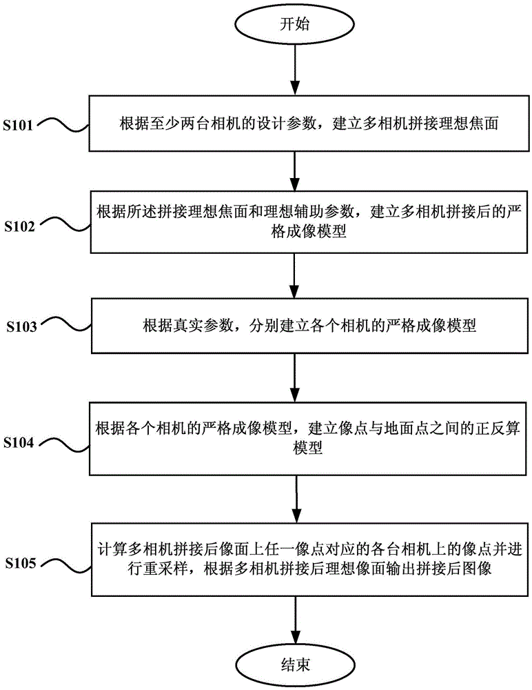
[0035] figure 1 A flowchart showing a multi-camera data stitching method based on a strict imaging model according to an embodiment of the present invention. Such as figure 1 As shown, the method includes:

[0036] Step 101, according to the design parameters of at least two cameras, establish an ideal focal plane for multi-camera stitching.

[0037] In one embodiment, the establishment of the multi-camera stitching ideal focal plane according to the design parameters of at least two cameras includes: reading the multi-camera design parameters, the camera design parameters including the number of probes and the number of overlapping pixels , the total field of view, and the focal length of the camera; calculate the number of probes on the ideal focal plane according to the number of probes and t...


PUM


Abstract

The invention provides a multi-camera data splicing method based on a strict imaging model. The method comprises steps that an ideal multi-camera splicing focal plane is established according to design parameters of at least two cameras; according to the ideal splicing focal plane and ideal auxiliary parameters, a strict imaging model after multi-camera splicing is established; according to actual parameters, a strict imaging model of each camera is established; according to the strict imaging models of the cameras, a positive and negative computation model between image points and ground points is established; after multi-camera splicing, image points of the cameras corresponding to any image point on an image are calculated, re-sampling is further carried out, after multi-camera splicing, an image after splicing is outputted from the ideal image plane. Through the method, multi-camera splicing precision can be improved, problems of low multi-camera splicing precision and poor stability in the prior art are solved, through experiment verification, splicing precision is stable, splicing is not influenced by an image texture status factor, and the splicing precision is high.

Description

technical field [0001] The invention relates to the field of optical remote sensing satellite camera imaging, in particular to a multi-camera data splicing method based on a strict imaging model. Background technique [0002] In the optical visible light remote sensing satellite imaging process, high resolution and wide field of view are still a pair of contradictions. At present, in order to ensure the acquisition of images with a higher spatial resolution and a certain width, the multi-chip TDICCD splicing method and the multi-camera splicing method are mostly used in the payload design. Among them, the multi-camera stitching process mostly uses the method based on feature point matching to process in the air domain or frequency domain. However, in remote sensing data engineering production, due to the low stability of the internal and external orientation elements of multiple cameras, the stitching accuracy is often not guaranteed. Remote sensing data generally use imag...

Claims


Application Information

Patent Timeline
Patent Type & Authority Applications(China)
IPC IPC(8): G06T3/00G06T3/40
CPCG06T3/4038G06T3/14
Inventor 肖倩汪红强马灵霞陈科杰
Owner SPACE STAR TECH CO LTD
Learn More