Fluorescent wheel and fluorescent conversion system
A fluorescent wheel and fluorescent technology, applied in the field of fluorescent conversion, can solve the problems of large size and complex structure, and achieve the effect of reducing the degree of coherence, simplifying the structure, and benefiting the overall size
- Summary
- Abstract
- Description
- Claims
- Application Information
AI Technical Summary
Problems solved by technology
Method used
Image

Examples
Embodiment 1
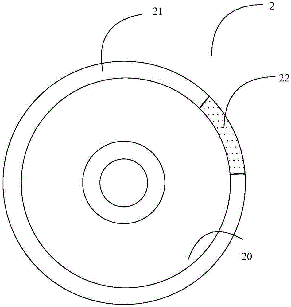
[0048] like figure 2 As shown, the embodiment of the present invention provides a fluorescent wheel 2 for receiving laser irradiation, including a phosphor area 21 and a laser scattering area 22 located on a reflective substrate 20; wherein: the phosphor area 21 is used for Fluorescence is emitted under excitation and reflected; the laser scattering area 22 is used to scatter the incident laser light and reflect it;
[0049] Here, the reflective substrate 20 refers to a substrate having a reflective surface.
[0050]Wherein, the fluorescent light generated by the fluorescent powder area 21 diverges in all directions, and the fluorescent light diverging relative to the surface of the reflective substrate 20 is reflected, and then all the fluorescent light is emitted from the front of the fluorescent wheel 2 along an emission angle range of about 180 degrees.
[0051] In the embodiment of the present invention, because the fluorescent wheel 2 can reflect the incident laser lig...
Embodiment 2
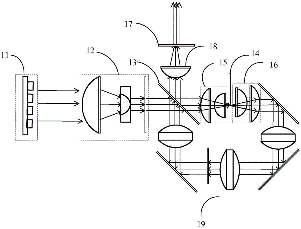
[0059] An embodiment of the present invention provides a fluorescence conversion system, such as Figure 5 As shown, it includes an excitation light source 3, a fluorescent wheel 2 and a light collecting device 4; wherein:
[0060] The fluorescent wheel 2 is used to accept the irradiation of the laser emitted by the excitation light source, including a phosphor area 21 and a laser scattering area 22 located on the reflective substrate 20; wherein: the phosphor area 21 is used to emit fluorescence under the excitation of the incident laser light and Reflected; the laser scattering area 22 is used to scatter the incident laser light and reflect it;
[0061] The light collecting device 4 is used for receiving the fluorescent light reflected by the fluorescent wheel 2 and the laser light and then mixing and emitting it.
[0062] Figure 5 Among the light beams emitted by the light collecting device 4 shown in , the dotted line represents the emitted fluorescent light, and the so...
Embodiment 3
[0077] The fluorescent conversion system provided in this embodiment, such as Figure 7 As shown, in addition to the excitation light source 3, the fluorescent wheel 2 and the light collecting device 4, the fluorescent conversion system also includes a color filter wheel 5;
[0078] color filter wheel 5, such as Figure 8 As shown, it includes a fluorescence filter area 51 and a laser transmission area 52; wherein the fluorescence filter area 51 is used to filter the fluorescence emitted by the light collection device; the laser transmission area 52 is used to transmit the laser light emitted by the light collection device.
[0079] In this embodiment, the fluorescent light and laser light filtered by the color wheel 5 are the final required light source.
[0080] implementation, such as Figure 7 As shown, the fluorescent wheel 2 and the color filter wheel 5 can be arranged coaxially. In this way, the fluorescent wheel 2 and the color filter wheel 5 can be controlled at th...
PUM
 Abstract
Description
Claims
Application Information
 - R&D
- Intellectual Property
- Life Sciences
- Materials
- Tech Scout
- Unparalleled Data Quality
- Higher Quality Content
- 60% Fewer Hallucinations
Browse by: Latest US Patents, China's latest patents, Technical Efficacy Thesaurus, Application Domain, Technology Topic, Popular Technical Reports.
© 2025 PatSnap. All rights reserved.Legal|Privacy policy|Modern Slavery Act Transparency Statement|Sitemap|About US| Contact US: help@patsnap.com