
CO2 heating heat pump system

A heat pump system and compressor technology, applied in heating systems, hot water central heating systems, household heating, etc., to achieve the effects of improving energy efficiency, increasing system energy consumption, and improving system energy efficiency

Active Publication Date: 2016-05-04
XI AN JIAOTONG UNIV
View PDF5 Cites 0 Cited by
  • Summary
  • Abstract
  • Description
  • Claims
  • Application Information

AI Technical Summary

Problems solved by technology

[0006] The object of the present invention is to provide a CO 2 Heating heat pump system to solve the existing heating heat pump system using CO 2 Working fluid problems exist when making transcritical CO 2 The heat pump system can be efficiently and stably applied to heating in the form of radiators in winter

Method used


Image

  • CO2 heating heat pump system
  • CO2 heating heat pump system
  • CO2 heating heat pump system

Examples


Embodiment Construction

[0025] The present invention will be described in further detail below in conjunction with the accompanying drawings.

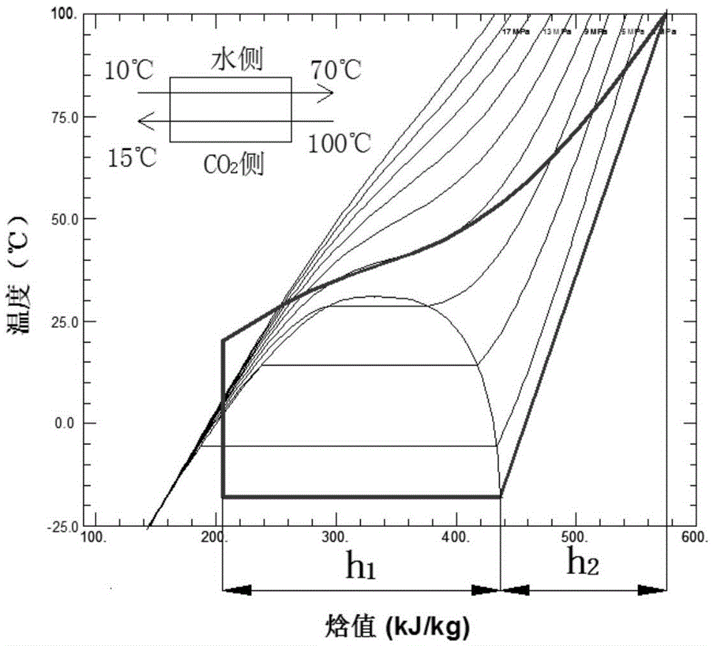
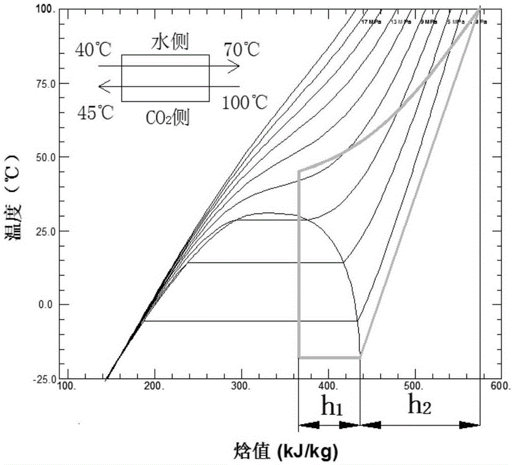
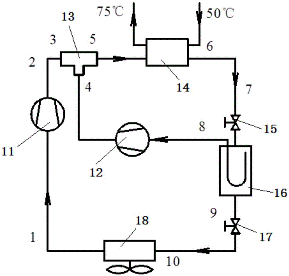
[0026] see image 3 and Figure 4 Shown, the present invention a CO 2 The heating heat pump system includes a first compressor 11 , a second compressor 12 , an ejector 13 , a gas cooler 14 , a first expansion valve 15 , a flash tank 16 , a second expansion valve 17 and an evaporator 18 .

[0027] The exhaust port of the first compressor 11 is connected to the inlet of the ejector 13, after ejecting the gas from the second compressor 12, the outlet of the ejector 13 is connected to the inlet of the gas cooler 14, and the refrigerant releases heat in the gas cooler 14, Heating water for heating; the outlet of the gas cooler 14 is connected to the inlet of the first expansion valve 15, the outlet of the first expansion valve 15 is connected to the inlet of the flash tank 16, the throttled refrigerant is separated in the flash tank 16, and the gas enters the se...


PUM


Abstract

The invention discloses a CO2 heating heat pump system. The CO2 heating heat pump system comprises a first compressor, a second compressor, an ejector, a gas cooler, a first expansion valve, a flashing tank, a second expansion valve and an evaporator; an exhaust port of the first compressor is connected with a first inlet of the ejector; an exhaust port of the second compressor is connected with a second inlet of the ejector; an outlet of the ejector is connected with a working medium inlet of the gas cooler; a working medium outlet of the gas cooler is connected with an inlet of the first expansion valve; an outlet of the first expansion valve is connected with an inlet of the flashing tank; a gas outlet of the flashing tank is connected with an inlet of the second compressor; and a liquid outlet of the flashing tank is connected with an inlet of the first compressor by the second expansion valve and the evaporator. The CO2 heating heat pump system applies two parallel compressors to reduce the performance attenuation problem of a CO2 heat pump at a high water return temperature (50 DEG C), uses the ejector for reducing the power consumption of the two compressors to improve the system energy efficiency, and is provided with an air return U-shaped pipe with an oil return hole in the flashing tank to guarantee an air sucking state of the compressors in an air state.

Description

【Technical field】 [0001] The invention belongs to the technical field of mechanical engineering and relates to a CO 2 Compound heat pump system. 【Background technique】 [0002] Mechanical compression heat pump technology uses a small amount of high-grade mechanical energy to complete the cycle of refrigerant in the system by using a compressor, extract heat from a lower temperature heat source and heat other media, that is, by consuming a small amount of high-grade energy, the low Grade energy is upgraded to high grade energy. The air source heat pump uses outdoor air as the heat source to heat or supply hot water. It is easy to install and use, has less environmental pollution, and its energy-saving effect is significantly higher than that of heating methods such as electric heating. However, there are some deficiencies in the operation of air source heat pumps in low temperature environments. For example, as the ambient temperature decreases, the indoor heat load demand ...

Claims


Application Information

Patent Timeline
IPC IPC(8): F24D3/18F25B31/00F25B41/00F25B41/31
CPCF24D3/18F25B31/00F25B41/00F25B2400/06
Inventor 曹锋杨东方金磊何永宁殷翔
Owner XI AN JIAOTONG UNIV
Learn More