
Frog compactor

A tamping machine, frog technology, applied in the field of machinery, can solve the problems of bulky, inflexible steering and forward movement, low work efficiency, etc., to achieve the effect of flexible steering and forward movement, low production cost, and high work efficiency

Inactive Publication Date: 2016-05-04
WUXI VOCATIONAL & TECHN COLLEGE
View PDF5 Cites 2 Cited by
  • Summary
  • Abstract
  • Description
  • Claims
  • Application Information

AI Technical Summary

Problems solved by technology

[0009] Due to the large size of the existing frog compactor, the work efficiency is low, and the steering and forward movement are inflexible

Method used

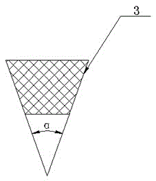

Image

  • Frog compactor
  • Frog compactor

Examples


Embodiment Construction

[0020] Below in conjunction with accompanying drawing, the present invention will be further described.

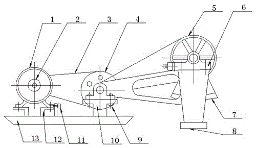
[0021] see as figure 1 —— figure 2 As shown, this specific embodiment adopts the following technical scheme: it includes a motor 1, an output shaft pulley 2, a V-belt 3, a large deceleration pulley 4, a large output pulley 5, a bearing seat 6, an eccentric block 7, and a rammer bottom plate 8. Connecting bolt 9, support frame 10, tensioning screw 11, motor support 12, base plate 13; the output shaft of the motor 1 is connected with the output shaft pulley 2, and the output shaft pulley 2 is connected to the deceleration by the V-belt 3 The large pulley 4 is connected; the output large pulley 5 is connected with the eccentric block 7, and a bearing seat 6 is installed on the shaft of the output large pulley 5; the bearing seat 6 is connected with the ram frame, and the bottom of the ram frame The tamp base plate 8 is connected; the support frame 10 is connected with the ...


PUM

PropertyMeasurementUnit
Qualityaaaaaaaaaa

Abstract

The utility model provides a frog compactor and relates to the technical field of machinery. The frog compactor comprises a motor, an output shaft pulley, a V belt, a large speed-reducing pulley, a large output pulley, bearing blocks, an eccentric block, a ramming head baseplate, a connecting bolt, a support frame, a tensioning screw, a motor bracket and a baseplate; an output shaft pulley is connected to an output shaft of the motor and also connected with the large speed-reducing pulley by means of the V belt; the large output pulley is connected with the eccentric block; one bearing block is mounted on a shaft of the large output pulley; the bearing block is connected with a ramming head rack and the ramming head baseplate is connected to the bottom of the ramming head rack; the support frame is connected with the bearing block of the large speed-reducing pulley by means of the connecting bolt; the motor bracket is mounted at the bottom of the motor; the motor bracket is connected with the motor by means of the tensioning screw; the baseplate is arranged at the bottoms of the support frame and the motor support. The frog compactor of the present invention is high in overall working efficiency, and more flexible in turning and moving forward.

Description

technical field [0001] The invention relates to the field of mechanical technology, in particular to a frog compactor. Background technique [0002] A compactor is a construction machine used to compact the ground. This vibratory compactor is used for compacting subsoil, especially for backfilling in trench work, river and pipeline work or garden and landscaping work. In traffic and road operations, vibratory rammers are mainly used for compacting and repairing operations on road shoulders. [0003] Due to the construction of the vibratory rammer, the vibratory rammer has a propulsion movement in the working direction. The surface treated by the tamping machine is not point-like, but flat and not fixed in position. The mode of propulsion movement of the rammer is directly related to the orientation of the vibrating mass of the rammer, especially the orientation of the vibrating mass relative to the central axis of the vibrating device or the axis of the rammer of the subs...

Claims


Application Information

Patent Timeline
IPC IPC(8): E02D3/074
CPCE02D3/074
Inventor 胡俊平周洁郑贞平
Owner WUXI VOCATIONAL & TECHN COLLEGE
Learn More