
Anodes for external plating of engine block tanks

An engine block and anode technology, applied to electrodes and other directions, can solve the problems of difficult control of key dimensions, difficulty in quality assurance of finished products, large changes in coating thickness, etc., to achieve controllable changes in coating thickness, avoid burrs on the edge of the coating, stable and uniform The effect of liquidity

Active Publication Date: 2018-07-10
南京隆尼精密机械有限公司
View PDF7 Cites 0 Cited by
  • Summary
  • Abstract
  • Description
  • Claims
  • Application Information

AI Technical Summary

Problems solved by technology

In the usual electroplating process, the electroplating solution is in a basically static environment, and the cations are passively moved to the inner surface of the cylinder as the cathode, and the resulting concentration difference makes the coating not tight, so it is easy to fall off, and the electroplating time is longer; and because The problem of concentration difference makes the coating thickness of the final product vary greatly and is difficult to control, which makes it difficult to control some key dimensions of the inner surface of the cylinder. Therefore, it is difficult to guarantee the quality of the finished product after electroplating
In the prior art, there is a technical scheme of circulating the electroplating solution to electroplate the nickel-silicon carbide composite layer on the inner circular surface of the cylinder, but because the anode structure itself and the cooperation with the cathode structure are not adaptable to the electroplating process, the final cylinder obtained Body products do not meet the needs of use

Method used


Image

  • Anodes for external plating of engine block tanks
  • Anodes for external plating of engine block tanks
  • Anodes for external plating of engine block tanks

Examples


Embodiment Construction

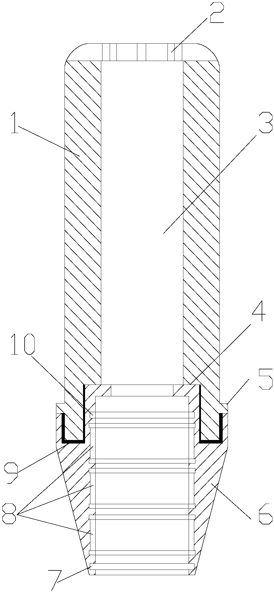
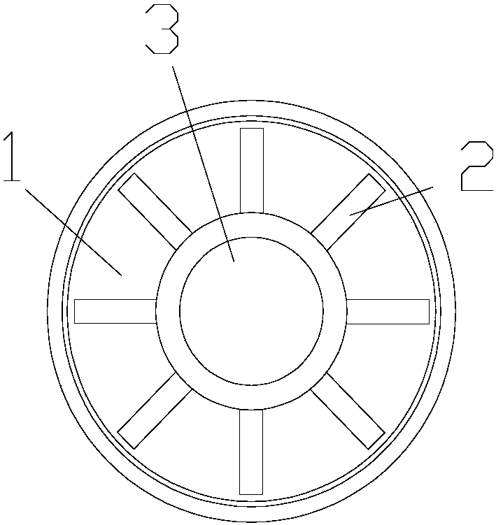
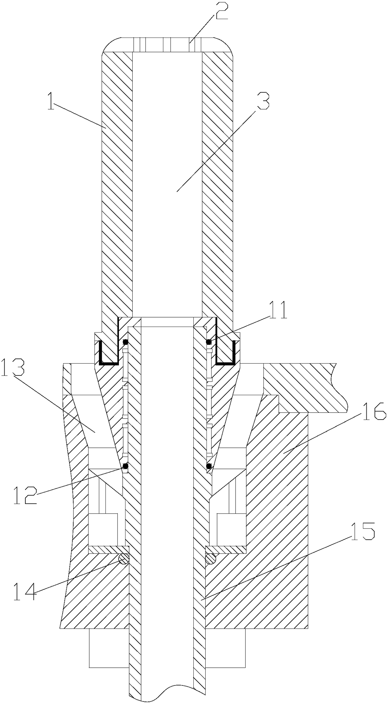
[0019] figure 1 It is a structural schematic diagram of the present invention, figure 2 for figure 1 top view, image 3 Use the installation structure diagram for the present invention, as shown in the figure: the anode used for electroplating outside the engine cylinder tank of this embodiment includes an anode body 1, and an electroplating solution return channel 3 is provided through the anode body 1, and the anode body 1 When in use, it is set inside the cylinder body, and the electroplating solution flows through the annular gap between the outer surface of the anode body 1 and the inner surface of the cylinder for backflow by the electroplating solution return channel 3 after electroplating; when in use, the anode itself 1 is generally fixed and Conductively connected to an anode seat 6. The anode seat 2 is directly installed on an installation base 16. Of course, the anode seat body can also be directly formed by integral molding, and the anode seat body is directly ...


PUM


Abstract

The invention discloses an anode for outside groove electroplating of an engine cylinder body. The anode comprises an anode body. An electroplating solution backflow channel is arranged on the anode body in a penetrating mode. The anode body is sleeved with the cylinder during use, and electroplating solutions flow through an annular gap between the outer surface of the anode body and the inner surface of the cylinder body and flow back through the electroplating solution backflow channel after electroplating. The anode is applicable to the electroplating solutions to form a flowing scheme for outside groove electroplating inside a cavity so as to form a flowing electroplating environment; the anode is convenient to install and use when used for cylinder body electroplating, the flowing electroplating solutions ensure that cations on a coating are replaced in real time, so that the concentration difference of the cations on the surface of a cathodic coating is basically not changed, large concentration difference is prevented from being formed, and variations in coating thickness are controllable; difference-free concentration as well as stable and uniform flowability ensure that the coatings are dense and compact, and the flowing electroplating solutions can take away the cations which are not combined with the coatings closely enough, so that loose combination is prevented; meanwhile, the structure of the anode can effectively prevent burrs from appearing at electroplated edges. Therefore, the electroplating quality is guaranteed.

Description

technical field [0001] The invention relates to a component of an electroplating device for an engine cylinder block, in particular to an anode used for electroplating in an outer cavity of a tank. Background technique [0002] As the main part of the engine, the cylinder block is used to form the combustion chamber together with the piston and the cylinder head, and provide the movement track for the piston assembly, thereby forming a power conversion environment. When the cylinder guides the piston to reciprocate continuously, the inner wall of the cylinder and the piston rub against each other for a long time and at high frequency, which reduces the useful power of the cylinder and consumes part of the energy. Therefore, there is electroplating on the inner wall in the prior art, and the electroplating coating is used to replace the cylinder liner to solve the above problems. In the usual electroplating process, the electroplating solution is in a basically static enviro...

Claims


Application Information

Patent Timeline
Patent Type & Authority Patents(China)
IPC IPC(8): C25D17/10C25D17/12C25D5/02
CPCC25D5/028C25D17/10C25D17/12
Inventor 赵发生刘智勇聂进
Owner 南京隆尼精密机械有限公司
Learn More