
Transfer machine for box girder side form

A side form and box girder technology, which is applied in the field of box girder side form transport trolleys, can solve the problems of narrow space in the enclosure, large transfer costs, narrow construction space, etc., and achieve the effect of ensuring construction progress and safe and fast transfer.

Active Publication Date: 2016-05-04
CHINA RAILWAY SHANGHAI ENGINEERING BUREAU GROUP CO LTD +1
View PDF6 Cites 8 Cited by
  • Summary
  • Abstract
  • Description
  • Claims
  • Application Information

AI Technical Summary

Problems solved by technology

[0003] However, for complex environments with narrow spaces, the lifting equipment cannot support it, and there is a great safety risk during hoisting and transshipment. At the same time, the transshipment speed is slow and the transshipment cost is high
For example, the Guangzhou Metro Line 21 construction bid 19, the Xiangzhong viaduct section adopts multi-connected continuous rigid structures. The viaduct of this project is located on the Guangshan Highway from Guangzhou to Zengcheng. The construction space is very narrow, and the distance between the structural side of the beam body and the retaining wall About 1.35m, and the other side of the structure is about 7.35m away from the fence wall. There are two-way four-lane roads outside the fence, and the space inside the fence is narrow. All formwork is steel formwork, which cannot be hoisted by automobile cranes and other machinery, and steel bars are hoisted , Formwork hoisting and dismantling are difficult to complete. The total length of the bridge is 2500m, with a total of 26 continuous rigid structures, the longest of which is 172m, the beam width is 24.9m, and the pier height is about 15m. The way and speed of formwork inversion also affect the construction progress and A key factor in cost

Method used


Image

  • Transfer machine for box girder side form
  • Transfer machine for box girder side form
  • Transfer machine for box girder side form

Examples


Embodiment Construction

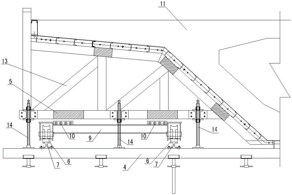
[0016] see figure 1 In this embodiment, the structural form of the box girder side form transfer tool for the box girder 11 is: on the support platform 4 below the box girder side form 13, two tracks are arranged in parallel along the direction of the transfer of the box girder side form 13 7. The traveling steel wheels 6 on both sides of the steel frame trolley are respectively supported on the track 7 at the corresponding position and can roll along the track. Rollers 10 are arranged in rows on the beam 9 of the steel frame trolley. The axes of the rollers 10 are Parallel to the track 7, and the roller 10 can roll on a fixed axis; the dropped box girder side form 13 can be supported on the roller 10 by the lower gusset plate 5 of the box girder side form, and the box girder side form 13 can be supported by the roller 10 The whole body moves to the outside for a certain distance on the steel frame trolley and then transfers on the track 7 with the steel frame trolley.

[001...


PUM


Abstract

The invention discloses a transfer machine for a box girder side form. The transfer machine for the box girder side form is characterized in that two tracks are arranged on a supporting platform in parallel under the box girder side form and in the transferring direction of the box girder side form; running steel wheels on two sides of a steel frame cart are supported on the tracks in the corresponding positions and can roll along the tracks; rollers are arranged on a cross beam of the steel frame cart in rows, the axes of the rollers are parallel to the tracks, and each roller can roll around a fixed axis; the falling box girder side form can be supported on the rollers by means of a lower joint plate of the box girder side form, is moved outwards on the steel frame cart overall by means of the rollers by a distance and then is transferred on the tracks along with the steel frame cart. The box girder side form directly falls onto the steel frame cart and is transferred on site, so that the box girder side form can be transferred safely and rapidly, and the construction progress is guaranteed.

Description

technical field [0001] The invention relates to a trolley for transporting box girder side forms, more specifically a transport tool for quickly reversing box girder side forms in a narrow space where hoisting and hoisting equipment cannot be used. Background technique [0002] In the existing technology, the dismantling of the side formwork of the box girder is usually performed by a crane first, then transported to the next site by a car, and then installed by a crane again. [0003] However, for the complex environment in a narrow space, the lifting equipment cannot support it, and there is a great safety risk during hoisting and transshipment. At the same time, the transshipment speed is slow and the transshipment cost is high. For example, the Guangzhou Metro Line 21 construction bid 19, the Xiangzhong viaduct section adopts multi-connected continuous rigid structures. The viaduct of this project is located on the Guangshan Highway from Guangzhou to Zengcheng. The const...

Claims


Application Information

Patent Timeline
IPC IPC(8): B65G35/00E01D21/00
CPCB65G35/00E01D21/00
Inventor 梁磊刘琳龙亮李念军徐康周向国王丁一李光均杨旻刘晓林
Owner CHINA RAILWAY SHANGHAI ENGINEERING BUREAU GROUP CO LTD
Learn More