
Deduster box

A dust collector and box technology, applied in the field of machinery, can solve the problems of reducing the working efficiency of the dust collector and the cleaning cycle is not long, and achieve the effects of stable structure, prolonging the cleaning cycle, and uniform gas volume.

Inactive Publication Date: 2016-05-04
CHONGQING ZONJO RENEWABLE RESOURCES DEV CO LTD
View PDF0 Cites 2 Cited by
  • Summary
  • Abstract
  • Description
  • Claims
  • Application Information

AI Technical Summary

Problems solved by technology

[0002] Dust collector (dust removal equipment) is a kind of equipment that separates dust from flue gas. According to its principle, dust collector can be divided into three categories: bag type dust collector, electrostatic dust collector, magnetic dust collector, among which bag type dust collector is The most common and commonly used equipment, but it has the following disadvantages in the actual production and use process: the fixed setting of the filter bag causes more gas to enter the filter bag on the side close to the air inlet, and within a certain period of time close to the air inlet The wind dust accumulated on the surface of the side filter bag is obviously more than that of other filter bags (although the filter bags are evenly arranged inside the dust collector), other filter bags do not play their role well, so the cleaning cycle is not long, and at the same time, reduces The working efficiency of the dust collector

Method used


Image

  • Deduster box
  • Deduster box

Examples


Embodiment Construction

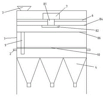
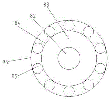
[0015] refer to Figure 1 to Figure 2 The embodiment of a dust collector box of the present invention will be further described.

[0016] A dust collector box body, including a box body 1, an air inlet 2, an air outlet 3, and an ash hopper 4, the bottom of the box body 1 is connected to the ash hopper 4, and it is characterized in that the side wall of the box body 1 is connected to the air inlet 2. The top of the chassis body 1 is connected to the air outlet 3, and the interior of the chassis body 1 is provided with a shock absorbing plate 6. The setting of the shock absorbing plate 6 plays a role of shock absorption and reduces the influence of the motor on the dust collector. An explosion-proof motor 7 is arranged above the damping plate 6. The setting of the explosion-proof motor 7 is to prevent the motor from sparking and improve the safety performance of the equipment. The bottom of the explosion-proof motor 7 is connected to a rotating shaft 81, and the rotating shaft 8...


PUM


Abstract

The invention specifically relates to a deduster box, which comprises a machine casing, air inlets, an air outlet, and ash buckets. A lower part of the machine casing is connected to the ash buckets; side walls of the machine casing are connected to the air inlets; and the top of the machine casing is provided with an air outlet. The machine casing is internally provided with a vibration absorbing plate; an explosion-proof electric machine is disposed on the top of the vibration absorbing plate; and the bottom of the explosion-proof electric machine is connected to a rotary shaft. The rotary shaft is connected to a rotary block, which is connected to one end of a filter-bag connection plate; the bottom of the filter-bag connection plate is connected to a filter bag; and the other end of the filter-bag connection plate is connected to a rotary plate. The rotary plate is in external connection with balls, which are uniformly arranged at an external side of the rotary plate and in tangent connection with the rotary plate. External sides of the balls are connected to a fixed board, which is in tangent connection with the balls, and the external side of the fixed board is connected to inner walls of the machine casing. Through a reasonable structure of the deduster box, the working efficiency of a deduster is increased, and a dust cleaning period of a filter bag is prolonged.

Description

technical field [0001] The invention relates to the technical field of machinery, in particular to a box body of a dust collector. Background technique [0002] Dust collector (dust removal equipment) is a kind of equipment that separates dust from flue gas. According to its principle, dust collector can be divided into three categories: bag type dust collector, electrostatic dust collector, magnetic dust collector, among which bag type dust collector is The most common and commonly used equipment, but it has the following disadvantages in the actual production and use process: the fixed setting of the filter bag causes more gas to enter the filter bag on the side close to the air inlet, and within a certain period of time close to the air inlet The wind dust accumulated on the surface of the side filter bag is obviously more than that of other filter bags (although the filter bags are evenly arranged inside the dust collector), other filter bags do not play their role well,...

Claims


Application Information

Patent Timeline
Patent Type & Authority Applications(China)
IPC IPC(8): B01D46/02B01D46/42
CPCB01D46/023B01D46/4236B01D2258/0283
Inventor 郭伟陈先勇战琦琦
Owner CHONGQING ZONJO RENEWABLE RESOURCES DEV CO LTD
Learn More