Eureka AIR delivers breakthrough ideas for toughest innovation challenges, trusted by R&D personnel around the world.

Method for designing gaps of end straight sections of diagonal few-leaf main springs and auxiliary springs

A straight section, slanted line technology, which is applied to the gap between the straight section at the end and the secondary spring of the slanted few-leaf main spring. Design requirements for linear variable cross-section leaf springs, etc.

Active Publication Date: 2016-04-27
山东恒日悬架弹簧股份有限公司
View PDF5 Cites 77 Cited by
  • Summary
  • Abstract
  • Description
  • Claims
  • Application Information

AI Technical Summary

Problems solved by technology

Since the calculation of the deformation at any position of the non-isomorphic slanted few-leaf leaf spring at any position is very complicated, so far, it has not been possible to provide a simple, accurate and reliable slanted-shaped few-leaf main spring with straight ends. The Design Method of the Clearance Between Section and Secondary Spring
[0004] Although some people have previously given the design method of a few inclined-line variable-section leaf springs, for example, Peng Mo and Gao Jun once gave a variable-section spring in "Automotive Engineering", 1992 (Volume 14) No. 3 The design and calculation method of the leaf spring, this method is mainly designed for the small oblique type variable cross-section leaf spring with the end isomorphic, and its shortcoming is that it cannot meet the small oblique type variable cross-section steel plate with the end non-equal structure The design requirements of the spring cannot meet the design of the gap between the main spring and the auxiliary spring at the contact point between the straight section of the end and the auxiliary spring of the main spring with a small oblique line and variable cross-section.
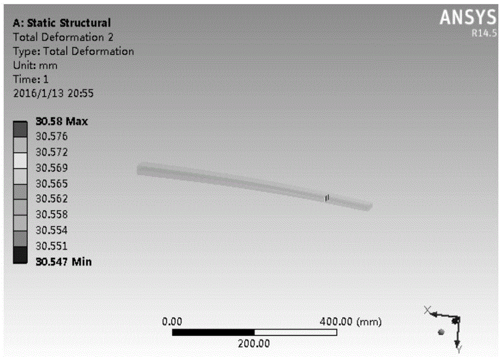
At present, although some people have used the ANSYS modeling and simulation method for the deformation of the non-isomorphic few-piece inclined-line variable-section main spring at the end of the straight section, but this method can only be used for the variable-section of the actual design structure. Simulation verification of the deformation of leaf springs cannot provide accurate analytical design formulas, nor can it meet the rapid development of vehicles and the development of modern CAD design software for suspension leaf springs

Method used


Image

  • Method for designing gaps of end straight sections of diagonal few-leaf main springs and auxiliary springs
  • Method for designing gaps of end straight sections of diagonal few-leaf main springs and auxiliary springs
  • Method for designing gaps of end straight sections of diagonal few-leaf main springs and auxiliary springs

Examples


Embodiment 1

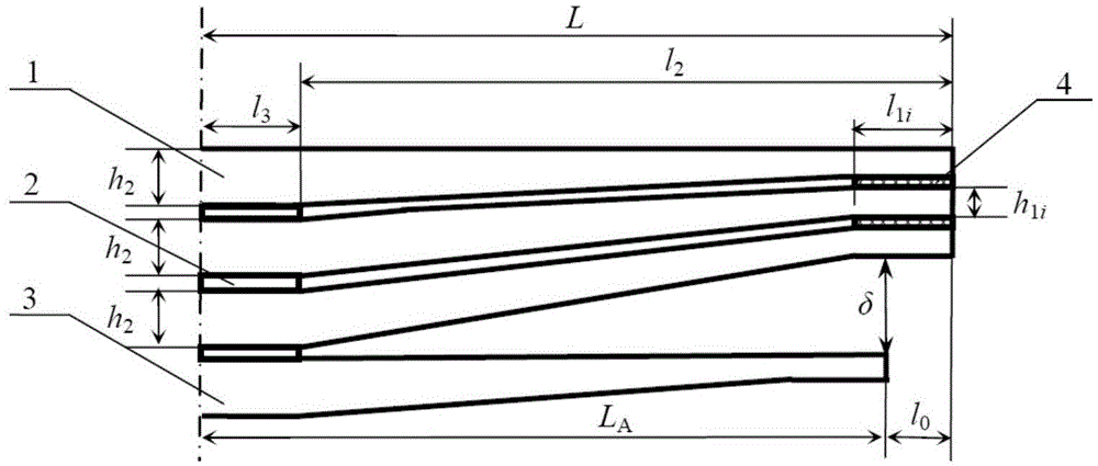
[0032] Example 1: The number of pieces of a few slash-type variable cross-section main springs is N=2, wherein, the half length of each piece of main spring is L=575mm, the width b=60mm, the elastic modulus E=200GPa, the straight section of the root thickness h 2 =11mm, half of the installation distance l 3 =55mm, the distance l from the root of the oblique line segment to the end point of the main spring 2 =L-l 3 =520mm; thickness h of the flat end section of the first main spring 11 =7mm, that is, the thickness ratio β of the oblique line segment of the first leaf main spring 1 =h 11 / h 2 =0.64, the thickness h of the flat end section of the second main spring 12 =6mm, that is, the thickness ratio β of the oblique line segment of the second main spring 2 =h 12 / h 2 =0.55; half the length L of the auxiliary spring A =465mm, the horizontal distance l between the secondary spring contact and the main spring end point 0 =L-L A =110mm, the contact point of the auxilia...

Embodiment 2

[0052] Example 2: The number of pieces of a few slash-type variable cross-section main springs is N=2, wherein, the half length of each piece of main spring is L=600mm, the width b=60mm, the elastic modulus E=200GPa, the straight section of the root thickness h 2 =14mm, half of the installation distance l 3 =60mm, the distance l from the root of the oblique line segment to the end point of the main spring 2 =L-l 3 =540mm; thickness h of the flat end section of the first main spring 11 =9mm, that is, the thickness ratio β of the oblique line segment of the first leaf main spring 1 =h 11 / h 2 =0.64; thickness h of the flat end section of the second main spring 12 =8mm, that is, the thickness ratio β of the oblique line segment of the second leaf main spring 2 =h 12 / h 2 =0.57; half the length L of the auxiliary spring A =510mm, the horizontal distance l between the auxiliary spring contact and the main spring end point 0 =L-L A =90mm, the auxiliary spring contact is ...


PUM

PropertyMeasurementUnit
Lengthaaaaaaaaaa
Widthaaaaaaaaaa
Elastic modulusaaaaaaaaaa

Abstract

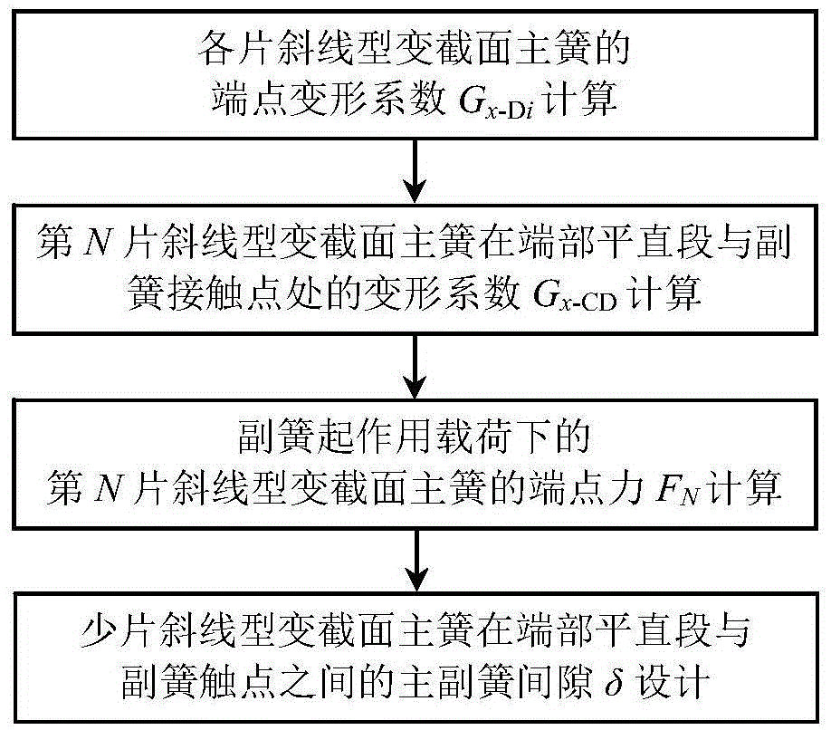
The invention relates to a method for designing gaps of end straight sections of diagonal few-leaf main springs and auxiliary springs, and belongs to the technical field of suspension steel plate springs. The method includes determining endpoint deformation coefficients of the various main springs and deformation coefficients G<x-CD> of contact points of the end straight sections of the N main springs and the auxiliary springs according to structure sizes and elastic modulus of the various diagonal variable-section main springs; acquiring endpoint force F<N> of the N main springs according to acting load of the auxiliary springs and the endpoint deformation coefficients of the various main springs; designing the main and auxiliary spring gaps between contact points of the end straight sections of the main springs and the auxiliary springs according to the thicknesses h<2> of roots of the N main springs, the endpoint force F<N> and the deformation coefficients G<x-CD>. The method has the advantages that as known from simulation verification, design values of the gaps of the end straight sections of the diagonal few-leaf variable-section main springs and the auxiliary springs can be accurately and reliably obtained by the aid of the method, and accordingly the product design level and performance and the vehicle ride comfort can be improved; the design and experiment costs can be reduced, and the product development speeds can be increased.

Description

technical field [0001] The invention relates to a vehicle suspension leaf spring, in particular to a method for designing the clearance between the flat end section and the auxiliary spring of an oblique type main spring with few leaves. Background technique [0002] For a few-piece variable-section leaf spring, in order to meet the requirements of variable stiffness, it is usually designed as the main and auxiliary springs, and through the gap between the main and auxiliary springs to ensure that the main and auxiliary springs are in contact and work together after a certain load is exceeded. It meets the design requirements for the stiffness of the leaf springs of the vehicle suspension under different load conditions. [0003] Because the force of the first piece of the few-piece variable-section main spring is complicated, it not only bears the vertical load, but also bears the torsional load and the longitudinal load. Each piece should be thicker, that is, in actual de...

Claims


Application Information

Patent Timeline
IPC IPC(8): F16F1/20G06F17/50
CPCF16F1/20G06F30/17
Inventor 周长城王炳超于曰伟王凤娟邵明磊赵雷雷张云山
Owner 山东恒日悬架弹簧股份有限公司
Why Eureka
Eureka Blog
Learn More