
Reinforced clamping mechanism for conveying round steel

A clamping mechanism and reinforced technology, applied in conveyors, conveyor objects, chucks, etc., can solve problems such as hidden dangers, insecurity, slipping, etc., to achieve the effect of convenient transportation and high safety

Active Publication Date: 2016-04-27
陈玲婷
View PDF6 Cites 22 Cited by
  • Summary
  • Abstract
  • Description
  • Claims
  • Application Information

AI Technical Summary

Problems solved by technology

[0002] The existing round steel is generally transported by a crane, and when the crane is transported, the round steel needs to be tied with a rope and then hoisted. Because the outer wall of the round tube is smooth, it is easy to slip from the rope, which poses a safety hazard
[0003] Moreover, the round steel is relatively heavy. If the speed is too fast when lifting, it is easy to shake and collide with the surroundings, which is not safe.

Method used


Image

  • Reinforced clamping mechanism for conveying round steel
  • Reinforced clamping mechanism for conveying round steel
  • Reinforced clamping mechanism for conveying round steel

Examples


Embodiment

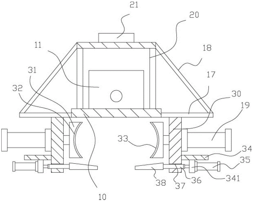
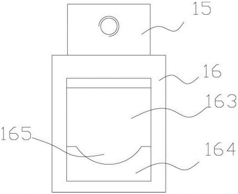
[0017] Example: see Figure 1 to Figure 3 As shown, a reinforced clamping mechanism for round steel transportation includes a conveying plate 10, a double output shaft driving motor 11 is fixed on the top surface of the middle part of the conveying plate 10, and there are elongated through grooves 12 on both sides of the conveying plate 10 , the top surface of the conveyor plate 10 on the left and right sides of the elongated through groove 12 is fixed with a support plate 13, the two ends of the transmission screw 14 are hinged on the corresponding two support plates 13, and the moving block 15 is screwed on the transmission screw 14 Among them, the moving block 15 is inserted into the corresponding elongated through groove 12, the lower part of the moving block 15 has a clamping block 16, the clamping block 16 is located below the conveying plate 10, and the opposite walls of the two clamping blocks 16 have Place the groove 161, a plurality of buffer springs 162 are fixed on...


PUM


Abstract

The invention discloses a reinforced clamping mechanism for conveying round steel. The reinforced clamping mechanism comprises a conveying plate; a double-extension-shaft drive motor is fixed to the top face of the middle portion of the conveying plate; long through grooves are formed in the two sides of the conveying plate; supporting plates are fixed to the positions, on the left side and the right side of the long through grooves, of the top face of the conveying plate; the two ends of a transmission screw rod are hinged to the two corresponding supporting plates; moving blocks are connected into the transmission screw rod in a screwing mode, and are inserted into the corresponding long through grooves; clamping blocks are arranged on the lower portions of the moving blocks and located below the conveying plate; the opposite walls of the two clamping blocks are provided with placing grooves; a plurality of buffer springs are fixed to the walls of the placing grooves; the buffer springs are fixed to main clamping end plates which are inserted into the placing grooves; the lower portions of the opposite walls of the two main clamping end plates are provided with bottom convex blocks; and arc-shaped placing grooves are formed in the top faces of the bottom convex blocks. The reinforced clamping mechanism can clamp the round steel firmly, facilitate conveying, prevent the round steel from falling off and has high safety.

Description

Technical field: [0001] The invention relates to the technical field of building material conveying equipment, and more specifically relates to a reinforced clamping mechanism for round steel conveying. Background technique: [0002] Existing round steel is generally carried by a crane when transported, and the round steel needs to be hoisted after being bound with a rope when the crane is transported. Because the outer wall of the round tube is smooth, it is easy to slip from the rope, which poses a safety hazard. [0003] Moreover, the round steel is relatively heavy. If the speed is too fast when lifting, it is easy to shake and collide with the surroundings, which is not safe. Invention content: [0004] The object of the present invention is to address the deficiencies of the prior art, and to provide a reinforced clamping mechanism for round steel transportation, which can firmly clamp the round steel, facilitates transportation, does not fall, and has high safety. ...

Claims


Application Information

Patent Timeline
Patent Type & Authority Applications(China)
IPC IPC(8): B65G47/90B25J15/10
CPCB25J15/106B65G47/90B65G2201/0223
Inventor 陈永林
Owner 陈玲婷
Learn More