
Auxiliary CT tube mounting structure

An installation structure and tube technology, applied in packaging, transportation and packaging, rigid containers, etc., can solve the problems of large workload and low work efficiency, and achieve the convenience of operation and use, reduce the difficulty of handling, and simple and fast installation and maintenance. Effect

Inactive Publication Date: 2016-04-27
GUANGDONG DEXIN MEDICAL TECH CO LTD
View PDF2 Cites 3 Cited by
  • Summary
  • Abstract
  • Description
  • Claims
  • Application Information

AI Technical Summary

Problems solved by technology

[0003] During the maintenance and disassembly process of the CT machine, due to the large volume of the CT tube and no bumps during the moving process, in the actual installation process, the maintenance personnel need to carry it repeatedly before they can accurately position the CT tube , and the CT tube is generally moved directly by manual handling, which has a large workload and low work efficiency

Method used


Image

  • Auxiliary CT tube mounting structure

Examples


Embodiment Construction

[0022] The present invention will be described below in conjunction with specific embodiments.

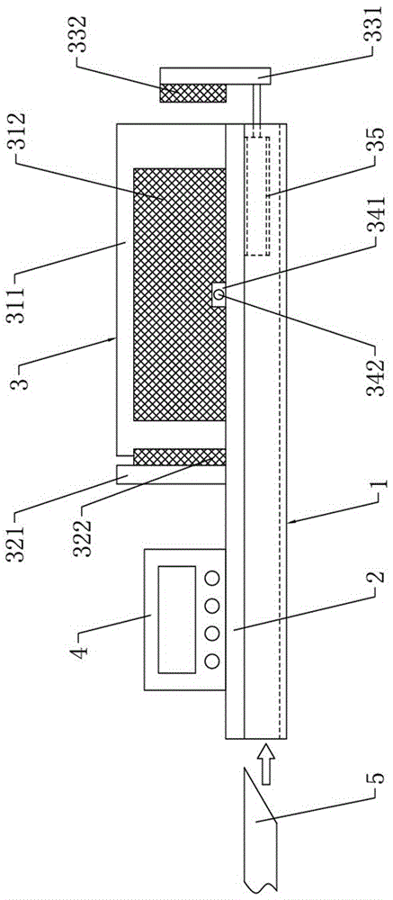
[0023] Such as figure 1 As shown, a CT tube auxiliary installation structure includes a fixed pallet 1 matched with the fork 5 of a forklift, the upper surface of the fixed pallet 1 is screwed with a fixed mounting plate 2 arranged horizontally and horizontally, and the fixed mounting plate 2 The front end of the upper surface is equipped with a CT tube clamping and positioning assembly 3 .

[0024] Further, the CT tube clamping and positioning assembly 3 includes a left positioning plate 311 and a rear positioning plate 321 which are respectively screw-mounted on the upper surface of the fixed mounting plate 2 and arranged vertically. The left positioning plate 311 is fixed and installed along the The left end edge of the plate 2 extends, and the rear positioning plate 321 is located at the rear end side of the left positioning plate 311 and extends along the left-right direction...


PUM


Abstract

The invention discloses an auxiliary CT tube mounting structure which is characterized in that a fixed mounting plate is bolted on the upper surface of a fixed tray; a CT tube clamping positioning component and a controller arranged on the upper surface of the fixed mounting plate; the CT tube clamping positioning component comprises a left side positioning plate, a rear side positioning plate and a front side positioning plate; a left side rubber cushion is mounted on the right end surface of the left side positioning plate; a rear side rubber cushion is mounted on the front end surface of the rear side positioning plate; a front side rubber cushion is mounted at the upper end part of the rear end surface of the front side positioning plate; an electric telescopic rod for driving the front side positioning plate to move forwards and backwards is mounted on the lower surface of the fixed mounting plate; a bolt mounting seat is bolted on the upper surface of the fixed mounting plate and located on the right end side of the left side positioning plate; and a positioning bolt is screwed on the upper end part of the bolt mounting seat. Through the structural design, the auxiliary CT tube mounting structure can effectively reduce the difficulty in carrying a CT tube in a CT tube mounting and maintenance process, so that the CT tube mounting and maintenance operation is simpler and quicker. Therefore, the auxiliary CT tube mounting structure has the advantages of novel design and convenience in operation and use.

Description

technical field [0001] The invention relates to the technical field of medical device maintenance and installation, in particular to an auxiliary installation structure of a CT tube. Background technique [0002] As a very important medical device, CT machine is widely used in various hospitals and plays a very important role in the process of disease diagnosis. Wherein, for a CT machine, the CT bulb inside it is the core component of the CT machine. [0003] During the maintenance and disassembly process of the CT machine, due to the large volume of the CT tube and no bumps during the moving process, in the actual installation process, the maintenance personnel need to carry it repeatedly before they can accurately position the CT tube , and the CT tube is generally moved directly by manual handling, which has a large workload and low work efficiency. Contents of the invention [0004] The object of the present invention is to provide a CT bulb auxiliary installation st...

Claims


Application Information

Patent Timeline
Patent Type & Authority Applications(China)
IPC IPC(8): B65D19/44B65D19/20
CPCB65D19/44B65D19/0004B65D2519/00815
Inventor 何美梨刘敏茹吴勤仲
Owner GUANGDONG DEXIN MEDICAL TECH CO LTD
Learn More