
Mini-sized vertical slot milling machine

A vertical milling and grooving machine technology, applied in milling machine equipment, milling machine equipment details, metal processing machinery parts, etc., can solve the problem of reducing the production speed of slotted commutators, increasing the production rate of unqualified products, and destroying the commutator structure And other issues

Inactive Publication Date: 2016-04-27
NINGBO SHENGKE COMMUTATOR
View PDF8 Cites 7 Cited by
  • Summary
  • Abstract
  • Description
  • Claims
  • Application Information

AI Technical Summary

Problems solved by technology

[0002] In the process of manufacturing slot-type commutators, it is necessary to mill grooves on the surface of the commutator that has been formed, but ordinary milling machines cannot mill grooves on the commutator, and it is inconvenient to change the commutator during the use of ordinary milling machines. The positioning of the commutator is easy to cause damage to the entire structure of the commutator when the commutator is milling slots. At the same time, the general slot milling machine cannot quickly replace the commutator, and the commutator needs to be removed and installed manually. This greatly reduces the production speed of slotted commutators and also increases the rate of defective products

Method used


Image

  • Mini-sized vertical slot milling machine
  • Mini-sized vertical slot milling machine
  • Mini-sized vertical slot milling machine

Examples


Embodiment

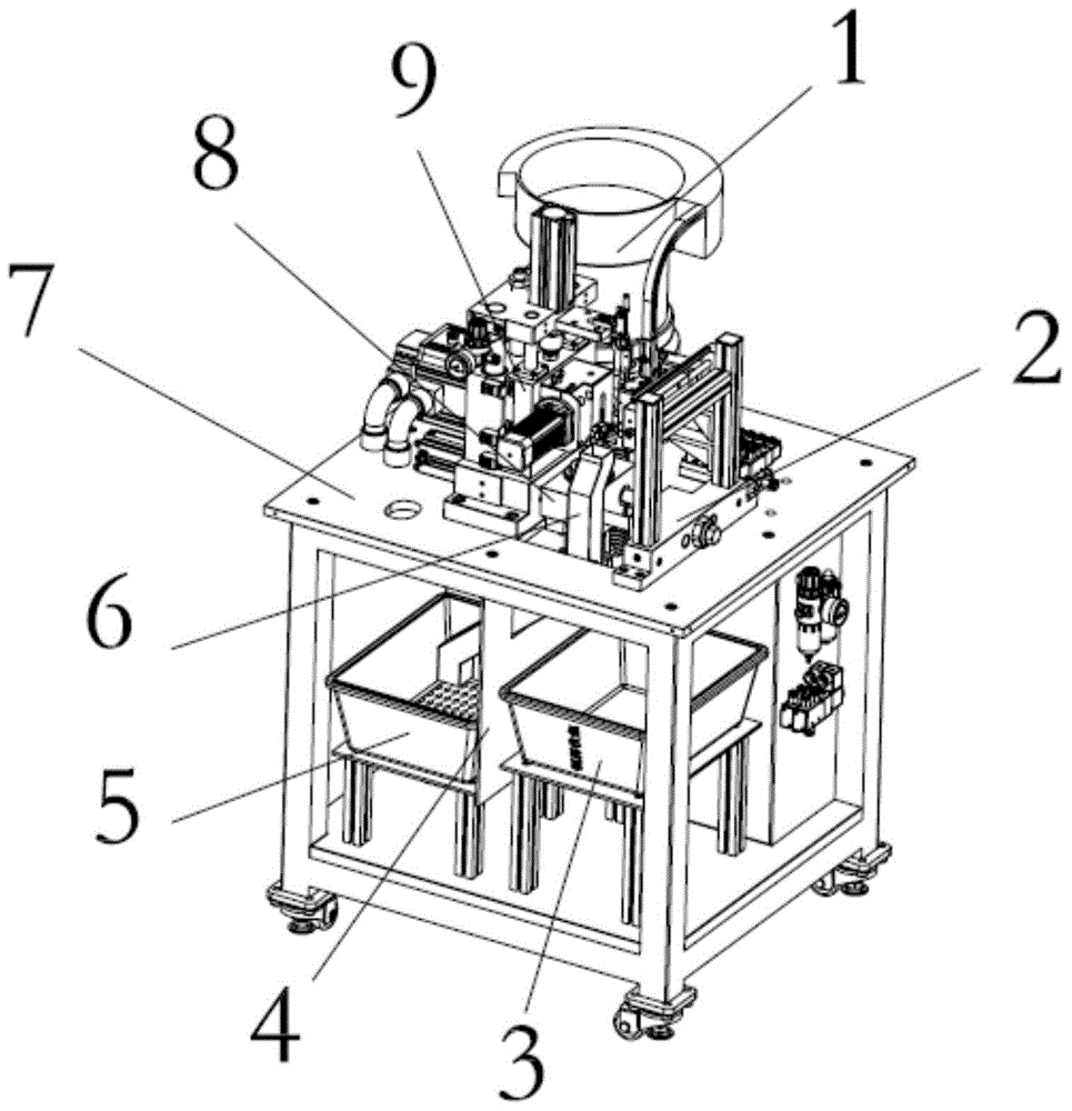
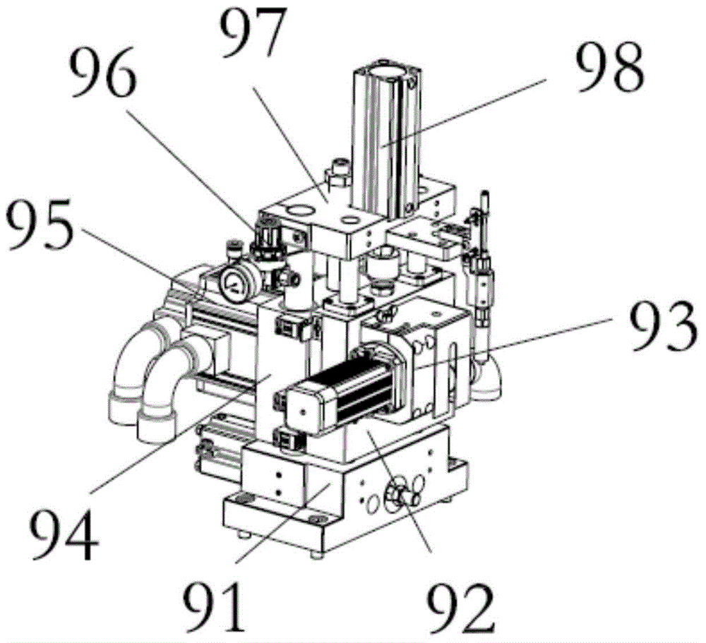
[0031]Place the commutator that has not been milled in the vibrating feeding tray 1. An optical fiber detection device is installed in the vibrating feeding tray 1 to reduce the wear of the commutator. Through the work of the vibrating feeding tray 1, the The commutators fall in a row along the feeding slide rail 11, and then the commutator stops falling through the material separation mechanism 27 on the feeding slide rail 11, and then the manipulator loading and unloading mechanism 2 starts, and the shifting manipulator 24 slides along the vertical slide rail bar 22, so that the vacuum feeding mechanism 26 installed horizontally at the lower end of the displacement manipulator 24 is located between the feeding positioning block 28 and the feeding slide rail 11, and then passes through the horizontal slide rail bar 23, Move the vacuum feeding mechanism 26 to the lower end of the feeding slide rail 11, then open the material separating mechanism 27, close the material separatin...


PUM


Abstract

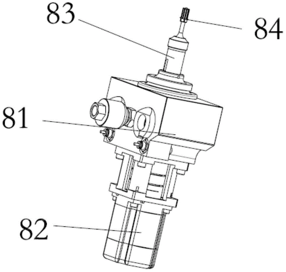
The invention relates to a mini-sized vertical slot milling machine. The machine comprises a rack platform, an indexing head assembling mechanism and a milling mechanism, wherein the milling mechanism is mounted at the left part of the surface of the rack platform, and a manipulator charging and discharging mechanism is vertically mounted at the right part of the surface of the rack platform; the indexing head assembling mechanism is vertically mounted at the front part between the milling mechanism and the manipulator charging and discharging mechanism; a vibrating charging tray is mounted on the rear side surface of the milling mechanism; the lower end of a charging slide rail of the vibrating charging tray is fixed on the side surface of the manipulator charging and discharging mechanism; and a blanking tube is mounted at a position, close to the indexing head assembling mechanism, between the milling mechanism and the manipulator charging and discharging mechanism. The machine has the characteristics of being simple in structure and convenient to operate, greatly improving the production speed of a mini-sized reverser, and decreasing the output rate of unqualified reversers.

Description

technical field [0001] The invention relates to the field of manufacturing miniature commutator slot milling machines, in particular to a miniature vertical slot milling machine. Background technique [0002] In the process of manufacturing slot-type commutators, it is necessary to mill grooves on the surface of the formed commutator, but general milling machines cannot mill grooves on commutators, and general milling machines are inconvenient to replace during use. The positioning of the commutator is easy to cause damage to the entire structure of the commutator when the commutator is milling slots. At the same time, the general slot milling machine cannot quickly replace the commutator, and the commutator needs to be removed and installed manually. This greatly reduces the production speed of the grooved commutator, and also increases the production rate of defective products. Contents of the invention [0003] The technical problem to be solved by the present inventio...

Claims


Application Information

Patent Timeline
Patent Type & Authority Applications(China)
IPC IPC(8): B23C3/28B23Q7/04B23Q7/10B23Q16/06B23Q5/34
Inventor 毛赛文孙瑞良陈飞邵信华李国法
Owner NINGBO SHENGKE COMMUTATOR
Learn More