Fluid control valve

A fluid control valve, opening and closing control technology, applied in control valves, fluid pressure actuators, valve details, etc., can solve the problems of complex structure, poor use convenience, inconvenient operation, etc., and achieve simple structure, small structure, The effect of reasonable design structure

Active Publication Date: 2016-04-20
SMC CORP
View PDF9 Cites 5 Cited by
  • Summary
  • Abstract
  • Description
  • Claims
  • Application Information

AI Technical Summary

Problems solved by technology

[0004] However, the above-mentioned fluid control valves in the past have assembled the above-mentioned needle valves, flow regulating valves or check valves, etc. inside the valve housing one by one, so the structure is complicated and large in many cases, and adjustment and operation are inconvenient and easy to use. In view of the problem of poor performance, a fluid control valve that is more compact and easy to use is expected.

Method used


Image

  • Fluid control valve
  • Fluid control valve
  • Fluid control valve

Examples


Embodiment Construction

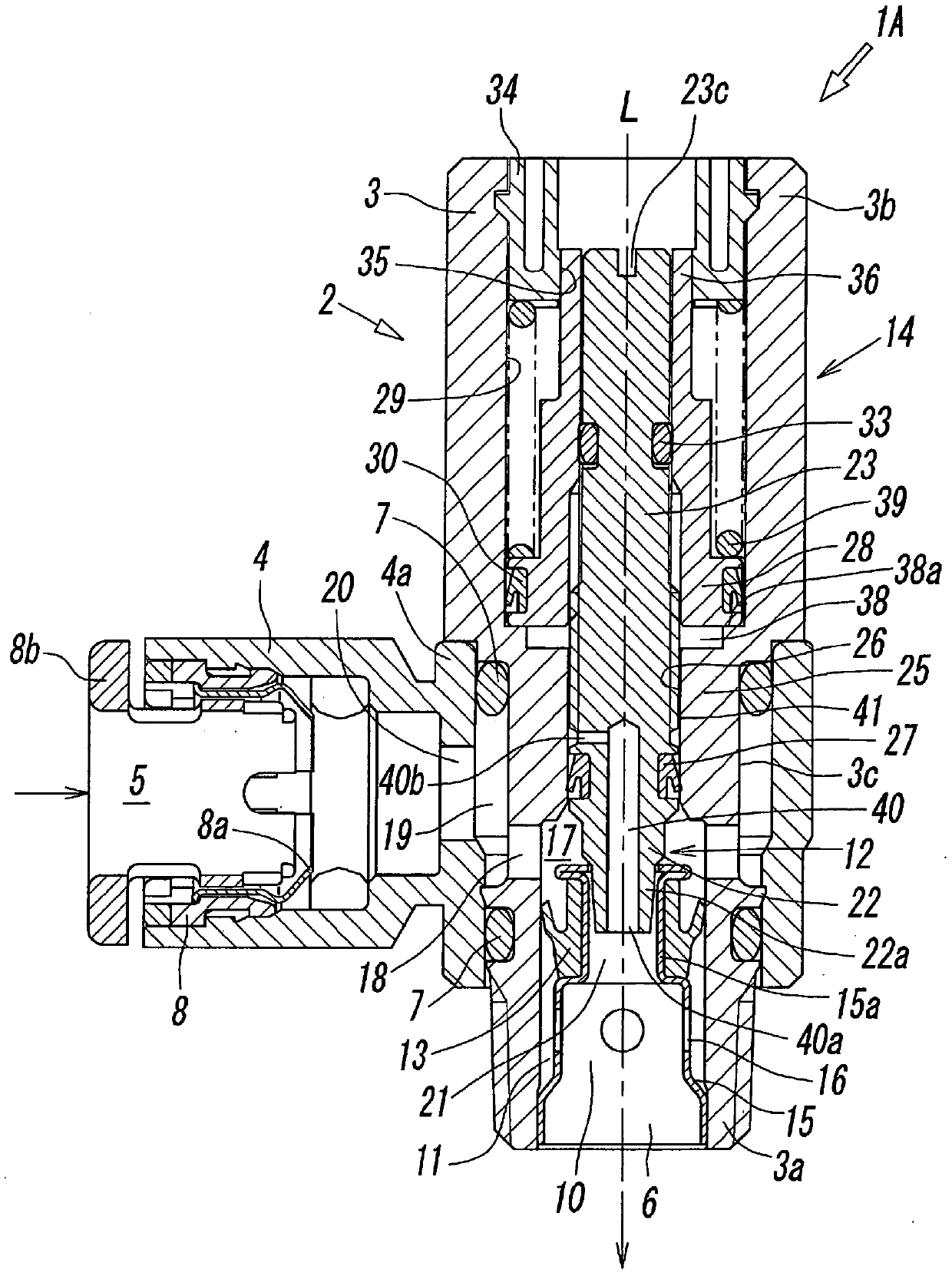
[0036] Figure 1 ~ Figure 4 The first embodiment of the fluid control valve according to the present invention is shown. The fluid control valve 1A is a meter-in control method for controlling the flow rate of the pressure fluid (for example, compressed air) supplied to a fluid pressure actuator such as a fluid pressure cylinder. Fluid control valve.

[0037] The fluid control valve 1A described above has a valve housing 2 having a first port through which a pressurized fluid is input and a second port through which a pressurized fluid is output. The valve housing 2 is composed of a main valve block 3 and a port valve block 4. The main valve block 3 is cylindrical and has the above-mentioned second port 6 on the side of the first end 3a, which is one end in the direction of the axis L of the central hole. The port valve block 4 has the above-mentioned first port 5 at the front end, and the fitting part 3c of the above-mentioned main valve block 3 can face each other around th...


PUM


Abstract

In the interior of a valve housing (2) equipped with a first flow path (10) and a second flow path (11) connecting a first port (5) and a second port (6) in parallel, there are provided a needle valve body (22), which opens / closes a throttle hole (21) in the first flow path (10), a check valve (13), which opens / closes the second flow path (11), and a piston (28), which controls the opening / closing of the needle valve body (22) through the interaction of the pressure of a fluid introduced into a pressure chamber (38) and the spring force of a compression spring (39). The needle valve body (22) is formed at the tip of a rod (23) attached to the piston (28), and a conduction hole (40) linking the throttle hole (21) and the pressure chamber (38) is formed in the interior of the rod (23) and the needle valve body (22).

Description

technical field [0001] The present invention relates to a fluid control valve for controlling the flow rate, pressure, etc. of pressurized fluid supplied to or discharged from an actuator such as a fluid pressure cylinder. Background technique [0002] When driving an actuator such as a fluid pressure cylinder, a fluid control valve that controls the flow rate, pressure, etc. of the pressure fluid supplied or discharged to the actuator is known, for example, as disclosed in Patent Document 1, Patent Document 2, etc. Fluid control valves of various structures. [0003] This kind of fluid control valve is generally composed of a needle valve that restricts the flow rate or pressure of the pressurized fluid by throttling the flow path, a flow regulating valve that opens and closes the flow path through the interaction of fluid pressure and spring force, or a pressure regulator that controls the flow path. A check valve, etc., in which the fluid flows in only one direction, a f...

Claims


Application Information

Patent Timeline
Patent Type & Authority Applications(China)
IPC IPC(8): F15B11/00F15B11/04F16K31/122
CPCF15B2211/8855Y10T137/7781F15B11/0413F15B13/02F15B13/0401F16K15/00
Inventor 肉户贤司
Owner SMC CORP
Why Eureka
Try Eureka