Switching method and electronic equipment
A technology of electronic equipment and switching instructions, which is applied in the electronic field and can solve problems such as poor flexibility
- Summary
- Abstract
- Description
- Claims
- Application Information
AI Technical Summary
Problems solved by technology
Method used
Image
Examples
Embodiment 1
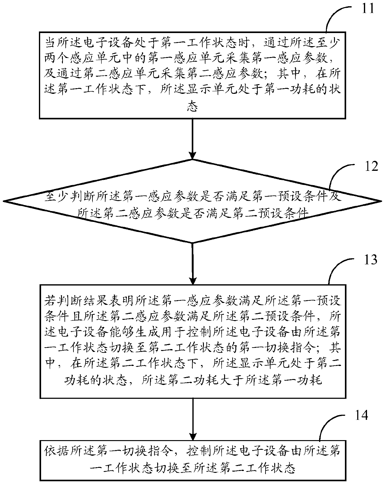
[0036] See figure 1 , an embodiment of the present invention provides a switching method, which is applied to an electronic device, where the electronic device includes a display unit and at least two sensing units, and the method may include:
[0037]Step 11: When the electronic device is in the first working state, collect the first sensing parameter through the first sensing unit of the at least two sensing units, and collect the second sensing parameter through the second sensing unit; wherein, in In the first working state, the display unit is in a first power consumption state.
[0038] Firstly, in the first working state, the display unit of the electronic device may be in a state of turning off the screen, that is, at this time, the electronic device may be in a standby state with low power consumption. The parameter information related to the electronic device can be collected in real time through at least two sensing units, or the parameters of the electronic device...
Embodiment 2
[0087] See image 3 , the embodiment of the present invention discloses a switching method, which is applied to an electronic device. The electronic device includes a display unit and a second sensing unit, and the electronic device is fixed on the first part of the operating body through a fixed body. The method may include:
[0088] Step 31: When the electronic device is in the first working state and the second part of the operating body is detected by the second sensing unit to perform the second operation, at least determine whether the operation range parameter corresponding to the second operation is A second preset condition is met; wherein, in the first working state, the display unit is in a first power consumption state.
[0089] In the embodiment of the present invention, in the first working state, the display unit of the electronic device may be in a state of turning off the screen, that is, the electronic device may be in a standby state with low power consumpti...
Embodiment 3
[0103] See Figure 4 , the embodiment of the present invention discloses an electronic device, including a display 1, at least two sensors 2 and a processor 3, wherein at least two sensors 2 and the processor 3 may be inside the electronic device. Specifically, when the electronic device is in the second working state of normal operation, corresponding image information can be output through the display 1 .
[0104] The at least two sensors 2 may be gravity sensors, infrared sensors or capacitive sensors, etc., which are not specifically limited in this application. In the embodiment of the present invention, the at least two sensors may specifically include a first sensor and a second sensor; wherein, the first sensor may be used to collect device parameters corresponding to the electronic device, and the device parameters can represent the operating body corresponding to the electronic device The first operation performed by the first part of the body; and the second sensor...
PUM
 Abstract
Description
Claims
Application Information
 - R&D Engineer
- R&D Manager
- IP Professional
- Industry Leading Data Capabilities
- Powerful AI technology
- Patent DNA Extraction
Browse by: Latest US Patents, China's latest patents, Technical Efficacy Thesaurus, Application Domain, Technology Topic, Popular Technical Reports.
© 2024 PatSnap. All rights reserved.Legal|Privacy policy|Modern Slavery Act Transparency Statement|Sitemap|About US| Contact US: help@patsnap.com


