Parameter measurement method for high-voltage and ultra-high-voltage direct-current transmission lines

A DC transmission line and UHV DC technology, which is applied in the field of parameter measurement of HV and UHV DC transmission lines, and can solve problems such as large measurement errors

Inactive Publication Date: 2016-04-20
YUNNAN POWER GRID CO LTD ELECTRIC POWER RES INST
View PDF8 Cites 10 Cited by
  • Summary
  • Abstract
  • Description
  • Claims
  • Application Information

AI Technical Summary

Problems solved by technology

[0005] In the embodiment of the present invention, a method for measuring parameters of high-voltage and ultra-high-voltage DC tra

Method used


Image

  • Parameter measurement method for high-voltage and ultra-high-voltage direct-current transmission lines
  • Parameter measurement method for high-voltage and ultra-high-voltage direct-current transmission lines
  • Parameter measurement method for high-voltage and ultra-high-voltage direct-current transmission lines

Examples


Embodiment 1

[0067] Such as figure 2 As shown, a parameter model of a single DC transmission line under the ground return mode with distributed parameter characteristics is constructed.

[0068] According to the parameter model of the single DC transmission line, the impedance per unit length is obtained as z=r+r g +jωl, which contains the earth resistance r g , the admittance per unit length is y=g+jωc 0 .

[0069] Among them, r is the resistance per unit length of the line, r g is the earth resistance per unit length, g is the ground conductance per unit length, l is the self-inductance per unit length of the line, c 0 is the ground capacitance per unit length, and ω is the angular frequency of the system.

[0070] According to the impedance and admittance of the unit length, the voltage and current incremental equations of the transmission line are respectively:

[0071] d U · d...

Embodiment 2

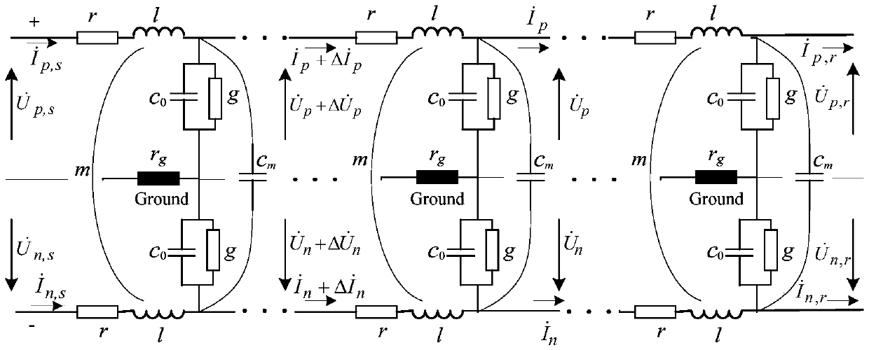
[0093] Such as image 3 As shown, a bipolar DC transmission line parameter model with distributed parameter characteristics is constructed.

[0094] According to the parametric model of the bipolar direct current transmission line, and the bipolar direct current transmission line is symmetrical about the tower, the self-impedance z=r+jωl and the self-admittance y=g+jωc of the two unipolar lines are obtained 0 Similarly, there is also a coupling capacitor c between the bipolar DC transmission lines m and mutual inductance m, and if the current in the bipolar line is unbalanced, there is a part of the unbalanced current through the earth resistance r g return.

[0095] According to the bipolar direct current transmission line parameter model, it can be drawn that the voltage increment equations on the positive pole (subscript p) and negative pole (subscript n) transmission lines are respectively:

[0096] d U ...


PUM

PropertyMeasurementUnit
Full lengthaaaaaaaaaa
Radiusaaaaaaaaaa

Abstract

The embodiments of the invention disclose a parameter measurement method for high-voltage and ultra-high-voltage direct-current transmission lines. According to the method, a direct-current transmission line model having distributed-parameter characteristics is constructed. Meanwhile, the expression of the impedance per unit length and the admittance per unit length, corresponding to the direct-current transmission line model, is established, wherein the earth resistance is involved. During the resolving process of a mathematical model, a homogeneous differential equation between the voltage and the current of the line in the boundary condition is solved to obtain a two-port power transmission line equation, wherein a telegraph equation is involved. After that, assisted by the open-circuit measurement means and the short-circuit measurement means at the end of the transmission line, the open-circuit impedance and the short-circuit impedance at the sending terminal of the transmission line are respectively measured. Furthermore, the distribution parameters of the direct-current transmission line are solved out and a computational formula for the earth resistance per unit length is given. According to the technical scheme of the invention, initial measurement data are acquired through constructing the transmission line model. Meanwhile, the two-port power transmission line equation is solved accurately. Therefore, the precise distribution parameters of the direct-current transmission line can be obtained.

Description

technical field [0001] The invention relates to the technical field related to high-voltage direct current transmission lines, in particular to a method for measuring parameters of high-voltage and extra-high voltage direct current transmission lines. Background technique [0002] HVDC transmission lines are typical long-distance distributed parameter circuits. During operation, because harmonic resonance may occur in the line, it is necessary to know the DC resistance of the transmission line, and the distributed capacitance and distributed inductance of the transmission line. In addition, the measured parameters of transmission lines are reliable data sources for system power flow stability calculations, and accurate transmission line models play an extraordinary role in the measurement of line parameters. [0003] In the prior art, the method for obtaining transmission line parameters is offline measurement. However, this method simply regards the short-circuit impedanc...

Claims


Application Information

Patent Timeline
IPC IPC(8): G01R31/00
CPCG01R31/00
Inventor 沈鑫闫永梅赵丹妮李月梅曹敏周年荣张林山黄星李鹏毛天常亚东
Owner YUNNAN POWER GRID CO LTD ELECTRIC POWER RES INST
Why Eureka
Try Eureka