
High-speed rotor blade flying-off test device and test method

A blade flying off, high-speed rotor technology, applied in the direction of internal combustion engine testing, etc., can solve the problems of increased test costs, difficult fan blade flying off tests, etc., to achieve the effect of ensuring the safety of rotation and ensuring safety

Active Publication Date: 2016-04-20
SUZHOU DONGLING TECH
View PDF7 Cites 38 Cited by
  • Summary
  • Abstract
  • Description
  • Claims
  • Application Information

AI Technical Summary

Problems solved by technology

After the blades fly off from the rotor, the working conditions of the rotor will be very different from the general high-speed rotating conditions, so the existing high-speed rotating test equipment is difficult to complete this rotor fan blade flying test
At present, the rotor fan blade fly-off test is performed by directly connecting the rotor to the engine, which will greatly increase the cost of the test

Method used


Image

  • High-speed rotor blade flying-off test device and test method
  • High-speed rotor blade flying-off test device and test method
  • High-speed rotor blade flying-off test device and test method

Examples


Embodiment Construction

[0036] The implementation of the present invention will be illustrated by specific specific examples below, and those skilled in the art can easily understand other advantages and effects of the present invention from the contents disclosed in this specification.

[0037] see Figure 1 to Figure 10. It should be noted that the structures, proportions, sizes, etc. shown in the drawings attached to this specification are only used to match the content disclosed in the specification, for those who are familiar with this technology to understand and read, and are not used to limit the implementation of the present invention. Limiting conditions, so there is no technical substantive meaning, any modification of structure, change of proportional relationship or adjustment of size, without affecting the effect and purpose of the present invention, should still fall within the scope of the present invention. The disclosed technical content must be within the scope covered. At the sa...


PUM


Abstract

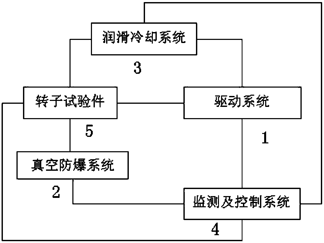
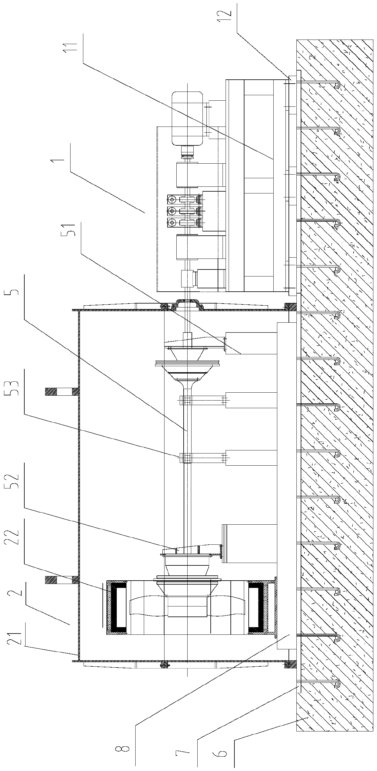
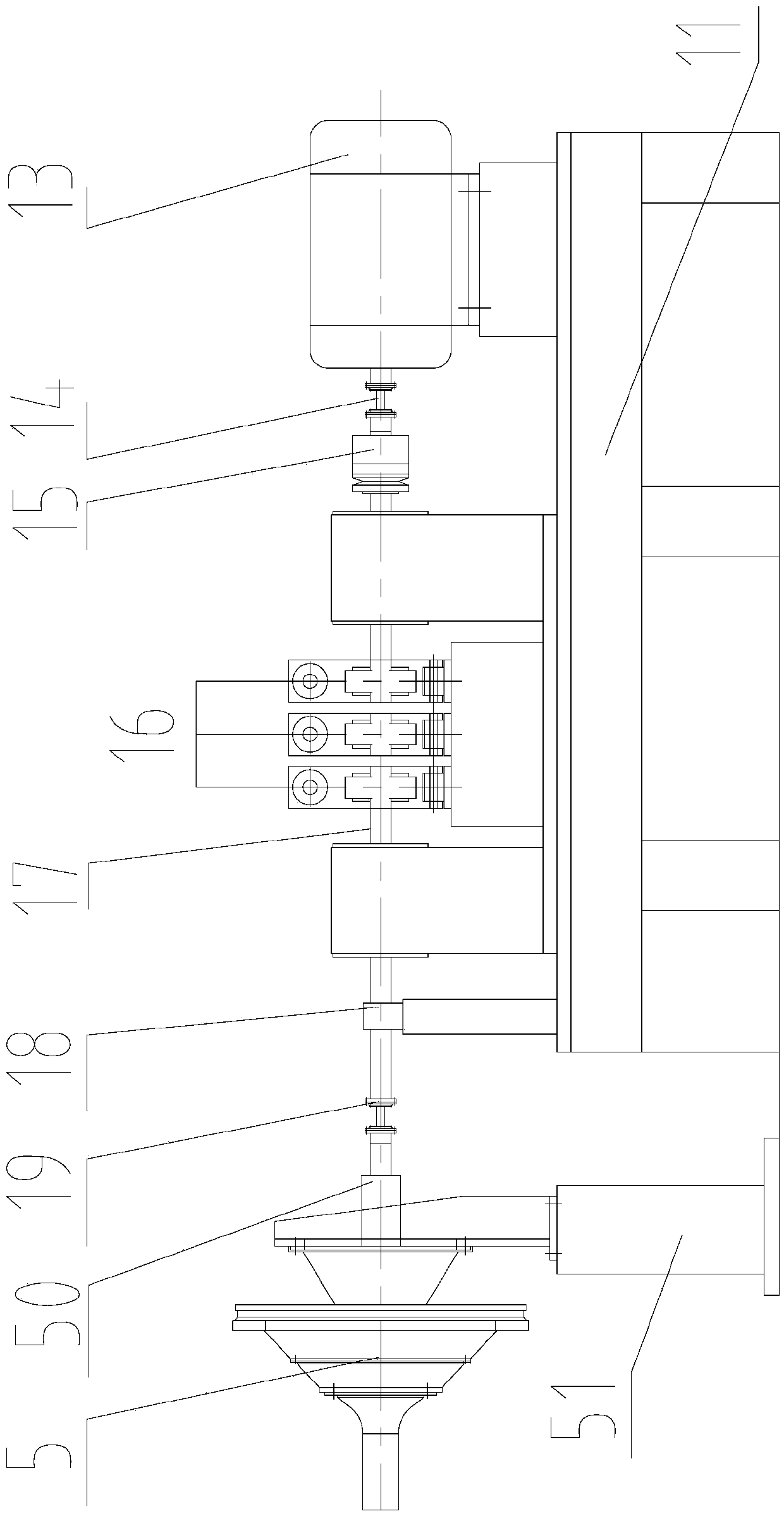
The invention provides a high-speed rotor blade flying-off test device, comprising a driving system, a vacuum anti-explosion system, a lubrication cooling system and a monitoring and control system. A driving motor is connected with a rotor test article through a transitional transmission mechanism, the vacuum anti-explosion system includes a vacuum chamber, the vacuum chamber is internally provided with a flying-loss protective cover, and a rotor rotation space and a blade flying-loss protective space are formed in the flying-loss protective cover, and are separated through a buffering separator plate. The buffering separator plate is arranged inside the flying-loss protective cover inside the vacuum chamber, after a blade on the rotor test article flies off, the blade stays in the blade flying-loss protective space, thus the blade that flies off does not collide with the rotating rotor test article, so that a test can be guaranteed to be carried out normally, at the same time, safety of test personnel and test equipment can be also effectively guaranteed, so as to ensure rotation safety of an engine rotor, and a technological means of an important empirical basis is provided for engine design finalizing.

Description

technical field [0001] The invention relates to the technical field of aero-engine rotor mechanics tests, in particular to a fly-off test device and test method for simulating engine rotor fan blades rotating at high speed. Background technique [0002] With the development of science and technology and the continuous progress of society, people's requirements for safe production have become higher and higher, especially the safety of high-speed rotating machinery has attracted more and more attention. For automobile engine flywheels, centrifugal compressor impellers, turbocharger rotors, aeroengine rotors and other devices, high-speed rotating equipment is often used to test their strength and safety. For example, the Chinese utility model patent (patent number: 201320527462.X) discloses a high-speed rotary testing machine, including a test chamber, a rotor system accommodated in the test chamber for the test rotor to test, a drive system and a control system for driving th...

Claims


Application Information

Patent Timeline
Patent Type & Authority Applications(China)
IPC IPC(8): G01M15/11
CPCG01M15/11
Inventor 徐曼元建学丁奕斌
Owner SUZHOU DONGLING TECH
Learn More