Remote optical fiber door cover switch monitoring system
A technology of switch monitoring and door cover, which is applied in measuring devices, using optical devices to transmit sensing components, converting sensor outputs, etc., can solve problems such as poor anti-electromagnetic interference ability, limited state transmission distance, and inconvenient power supply. Achieve the effect of strong anti-electromagnetic interference ability, realize remote intelligent monitoring, and reduce manual labor
- Summary
- Abstract
- Description
- Claims
- Application Information
AI Technical Summary
Problems solved by technology
Method used
Image
Examples
Embodiment 1
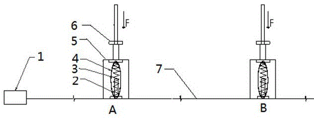
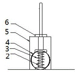
[0030] see figure 1 , figure 1 It is a schematic diagram of the structure and composition of Embodiment 1 of the remote optical fiber door switch monitoring system of the present invention. In the optical fiber door switch state monitoring system of this embodiment, the transmission optical fiber is connected to the optical time domain reflectometer 1 (hereinafter referred to as OTDR), and the optical fiber switch sensing device is connected to the transmission optical fiber 7, and the optical fiber switch sensor The device is installed at the corresponding position of the door cover to sense the switch state of the door cover; the optical path of the transmission fiber 7 is connected with the optical fiber ring 4 in the optical fiber switch sensing device, and the OTDR1 is used to detect the backscattering curve of the entire optical fiber link.
[0031] The structural composition of the optical fiber switch sensor device includes a spring 3 , a spring guard 2 , a moving adj...
Embodiment 2
[0047] please see Figure 7 , Figure 7 It is a schematic diagram of the structure and composition of Embodiment 2 of the remote fiber optic door cover switch monitoring system of the present invention. In this embodiment, two optical fiber switch sensing devices of the same type are connected to the transmission optical fiber 7. In the optical fiber switch sensing device, when the moving adjustment part 6 is not stressed and the optical fiber coil 4 is under a small spring tension, the state is circular, and Both, on the other hand, the optical fiber ring 4 is elliptical. The two optical fiber switch sensing devices are located at A and B respectively.
[0048] When the door cover is in the open state, that is, when there is no force by the arrow F, the optical fiber coil 4 is formed into a circle by the small tension of the spring 3, such as Figure 7 , when the force F is applied to the moving adjustment part 6, the state of the optical fiber coil and the spring is as fo...
PUM
 Abstract
Description
Claims
Application Information
 - R&D
- Intellectual Property
- Life Sciences
- Materials
- Tech Scout
- Unparalleled Data Quality
- Higher Quality Content
- 60% Fewer Hallucinations
Browse by: Latest US Patents, China's latest patents, Technical Efficacy Thesaurus, Application Domain, Technology Topic, Popular Technical Reports.
© 2025 PatSnap. All rights reserved.Legal|Privacy policy|Modern Slavery Act Transparency Statement|Sitemap|About US| Contact US: help@patsnap.com


