Marine lighting and sighting support

A cable-guide and marine-use technology, applied in theodolite and other directions, can solve problems such as time-consuming, system deviation accumulation increases, and high precision requirements for the placement of engine room support frames, so as to improve work efficiency, reduce safety hazards, and simplify the operation process. Effect

Active Publication Date: 2016-04-20
GUANGZHOU SHIPYARD INTERNATIONAL LTD
View PDF3 Cites 0 Cited by
  • Summary
  • Abstract
  • Description
  • Claims
  • Application Information

AI Technical Summary

Problems solved by technology

The support of the above-mentioned structure has the following defects when the hull is pulled by the line to see the light: (1) When determining the center of the axis, in addition to the laser theodolite, the theoretical height of the pulling axis of the horizontal pipe is also required, which is a cooperative operation between two processes, and there are many processes , due to the complex environment in the engine room area, it is inconvenient to cooperate with multiple processes and takes a long time; (2) Theoretically, the center of the axis and the center of the rudder intersect vertically in three-dimensional space, and it is required to place a laser theodolite at the intersection position to determine it. Due to the limitation of tooling, the laser machine can only be installed twice to determine the center of the shaft and the center of the rudder respectively, resulting in an increase in the accumulation of system deviations; (3) After the center of the shaft is determined, it is necessary to draw a steel wire through the centers of the front and rear shafts. Long, the deflection of the steel wire will affect the accuracy of the cable viewing light; (4) The current support has higher requirements for the placement accuracy of the cabin support frame

Method used


Image

  • Marine lighting and sighting support
  • Marine lighting and sighting support
  • Marine lighting and sighting support

Examples


Embodiment Construction

[0048] The technical solutions of the present invention will be further described below in conjunction with the accompanying drawings and through specific implementation methods.

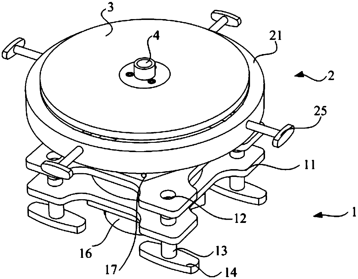
[0049] Such as Figures 1 to 14 As shown, in the embodiment of the present invention, the ship's stay wire viewing support includes a Z-axis lifting bracket 1, an XY-axis moving assembly 2 and a fixed plate 3, wherein the XY-axis moving assembly 2 is arranged on the top of the Z-axis lifting bracket 1, The reciprocating movement in the vertical direction can be realized through the Z-axis lifting bracket 1. The fixed disk 3 is arranged on the XY-axis moving assembly 2 to support the laser theodolite. The fixed disk 3 can realize the X-axis and X-axis in the horizontal direction through the XY-axis moving assembly 2. Y-axis movement.

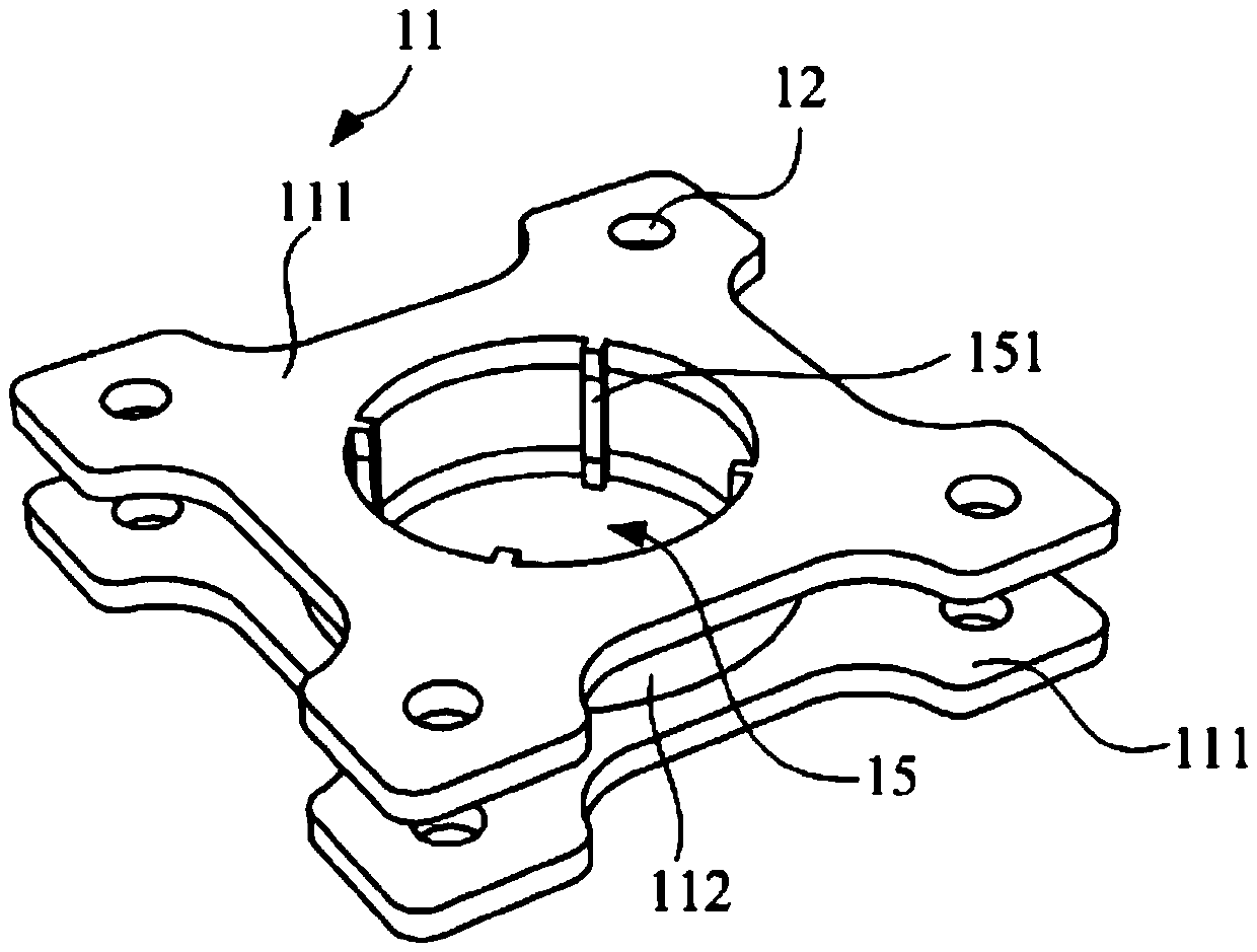
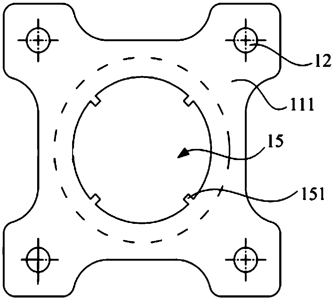
[0050] The Z-axis lifting bracket 1 includes a bracket body 11, and the four corners of the bracket body 11 are provided with a first threaded hole 12 along the Z-axi...


PUM


Abstract

The invention discloses a marine lighting and sighting support. The marine lighting and sighting support comprises a Z-axis hoisting bracket, an XY-axis movable assembly and a fixed disc, wherein the XY-axis movable assembly is arranged at the top of the Z-axis hoisting bracket and can do reciprocating motion along the vertical direction through the Z-axis hoisting bracket; the fixed disc is arranged on the XY-axis movable assembly and is used for supporting a laser theodolite; and the fixed disc can realize the movement of an X axis and a Y axis in the horizontal direction through the XY-axis movable assembly. The fixed disc for supporting the laser theodolite is arranged on the XY-axis movable assembly and the XY-axis movable assembly is arranged on the Z-axis hoisting bracket, so that the fixed disc and the laser theodolite I can move along an X-axis, Y-axis and Z-axis space to do three-dimensional motion; the laser theodolite can be arranged at a theoretical crossed-point position of an axis center and a rudder center; the axis center and the rudder center can be determined by only one time of swinging; and compared with the prior art, the marine lighting and sighting support provided by the invention has the advantages that an operation flow is simplified and the accuracy of lighting and sighting is improved.

Description

technical field [0001] The invention relates to the technical field of shipbuilding, in particular to a ship-used guy wire optical support. Background technique [0002] At present, the laser theodolite is mainly used to determine the center of the axis and the rudder center of the ship hull. In actual operation, the support is needed as the support of the laser theodolite. The existing support for supporting the laser theodolite can only move along the X and Y axis directions on the horizontal plane, and the laser theodolite needs to be placed twice. The rudder center is determined by the No. 0 rib where the center line of the traction dock sample and the rudder line are located. The support of the above-mentioned structure has the following defects when the hull is pulled by the line to see the light: (1) When determining the center of the axis, in addition to the laser theodolite, the theoretical height of the pulling axis of the horizontal pipe is also required, which i...

Claims


Application Information

Patent Timeline
IPC IPC(8): G01C1/02
CPCG01C1/02
Inventor 吴泽民刘子波陈俊贤
Owner GUANGZHOU SHIPYARD INTERNATIONAL LTD
Why Eureka
Try Eureka