Magnetic measurement positioning device and method for monitoring slope deep displacement by utilizing magnetic measurement positioning device
A deep displacement and magnetic measurement technology, which is applied in the field of magnetic positioning measurement, can solve the problems that the displacement value cannot be calculated and the sensor is used too much.
- Summary
- Abstract
- Description
- Claims
- Application Information
AI Technical Summary
Problems solved by technology
Method used
Image
Examples
Embodiment 1
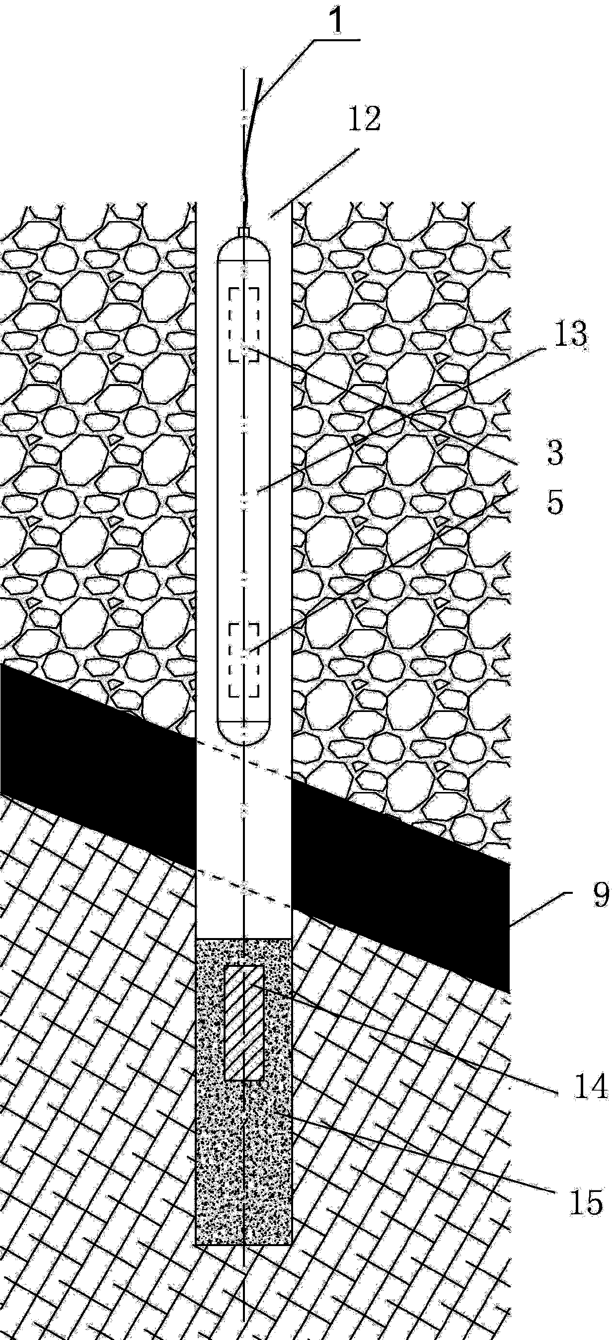
[0050] Such as Figure 4 and Figure 5 As shown, a magnetic positioning device includes a package casing 6, a pair of guide wheels 2 are installed on the package casing 6 along the upper and lower parts of the axial direction, the first three-dimensional fluxgate sensor 3 is installed on the upper part of the package casing 6, and the second The two-dimensional and three-dimensional fluxgate sensor 5 is installed in the lower part of the package shell 6, the first three-dimensional fluxgate sensor 3 and the second three-dimensional fluxgate sensor 5 are respectively connected to the signal acquisition module 4 through wires, and the signal acquisition module 4 is connected to the protruding The power supply and signal transmission cables 1 of the encapsulation shell 6 are connected, and the distance between the first three-dimensional fluxgate sensor 3 and the second three-dimensional fluxgate sensor 5 is kept constant, and the distance ranges from 1 to 1.5 meters.
[0051] T...
Embodiment 2
[0055] The landslide structure monitored by the method of the present invention and the positional relationship diagram of the deep displacement monitoring hole and the landslide are as follows figure 1 shown;
[0056] A method for monitoring the deep displacement of a landslide by using the above-mentioned magnetic positioning device, the method includes the following steps:
[0057] Step 1: For the landslide body 7 that needs to be monitored, drill down from the surface of the landslide body 7 to form a monitoring hole 8, and drill the monitoring hole 8 to the sliding bed 10 below the sliding belt 9;
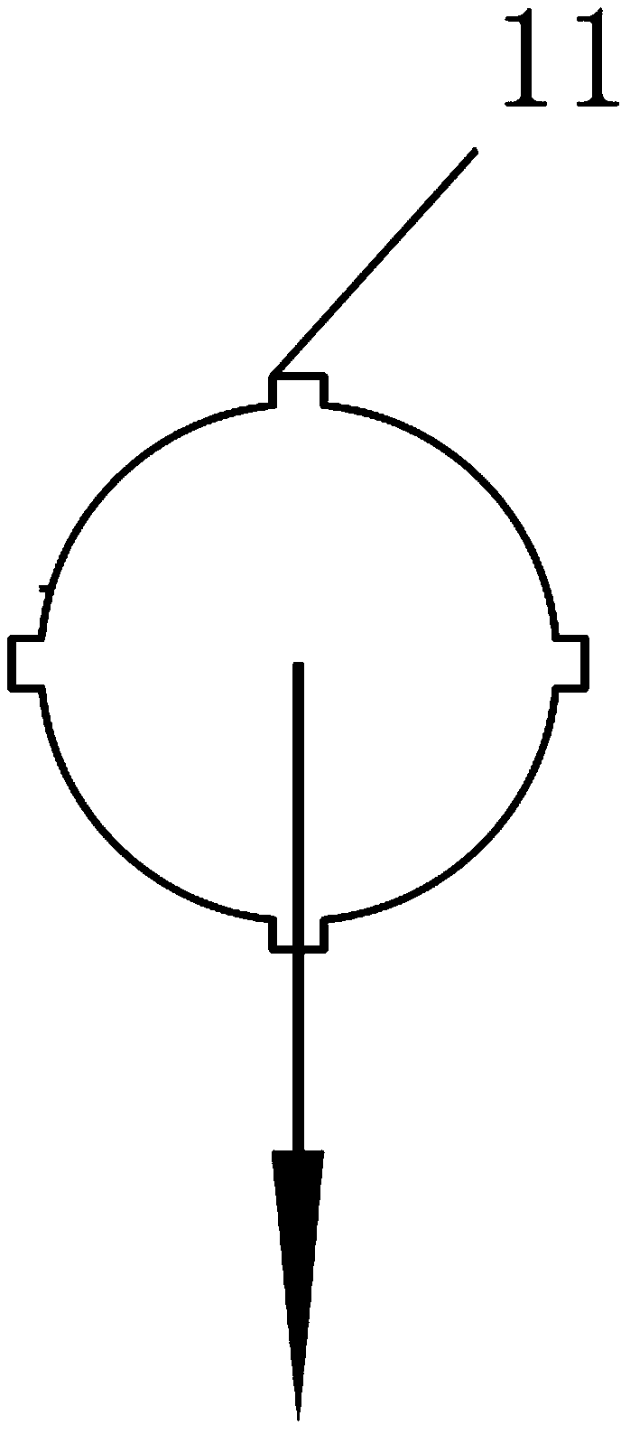
[0058] Step 2: install the inclinometer tube 12 with two sets of guide grooves 11 in the monitoring hole 8, the two sets of guide grooves 11 are perpendicular to each other, and the connecting direction of one set of guide grooves 11 is consistent with the sliding direction of the landslide body 7;
[0059] Step 3: In the initial stage of landslide deformation monitoring, use...
PUM
 Abstract
Description
Claims
Application Information
 - R&D
- Intellectual Property
- Life Sciences
- Materials
- Tech Scout
- Unparalleled Data Quality
- Higher Quality Content
- 60% Fewer Hallucinations
Browse by: Latest US Patents, China's latest patents, Technical Efficacy Thesaurus, Application Domain, Technology Topic, Popular Technical Reports.
© 2025 PatSnap. All rights reserved.Legal|Privacy policy|Modern Slavery Act Transparency Statement|Sitemap|About US| Contact US: help@patsnap.com


