
Engine multi-point power take-off structure

An engine and multi-point technology, applied to the frame of the engine, machine/engine, transmission device, etc., can solve the problems of poor structural adaptability, reduce vehicle parts, ensure consistent assembly quality, and reduce vehicle costs Effect

Active Publication Date: 2018-10-09
GUANGXI YUCHAI MASCH CO LTD
View PDF8 Cites 0 Cited by
  • Summary
  • Abstract
  • Description
  • Claims
  • Application Information

AI Technical Summary

Problems solved by technology

[0004] The purpose of the present invention is to provide a multi-point power take-off structure of the engine, so as to overcome the disadvantage of poor structural adaptability between the multiple power output ends of the engine and the rear-mounted gear chamber engine using the transfer case

Method used


Image

  • Engine multi-point power take-off structure
  • Engine multi-point power take-off structure
  • Engine multi-point power take-off structure

Examples


Embodiment Construction

[0019] The specific embodiments of the present invention will be described in detail below in conjunction with the accompanying drawings, but it should be understood that the protection scope of the present invention is not limited by the specific embodiments.

[0020] Unless expressly stated otherwise, throughout the specification and claims, the term "comprise" or variations thereof such as "includes" or "includes" and the like will be understood to include the stated elements or constituents, and not Other elements or other components are not excluded.

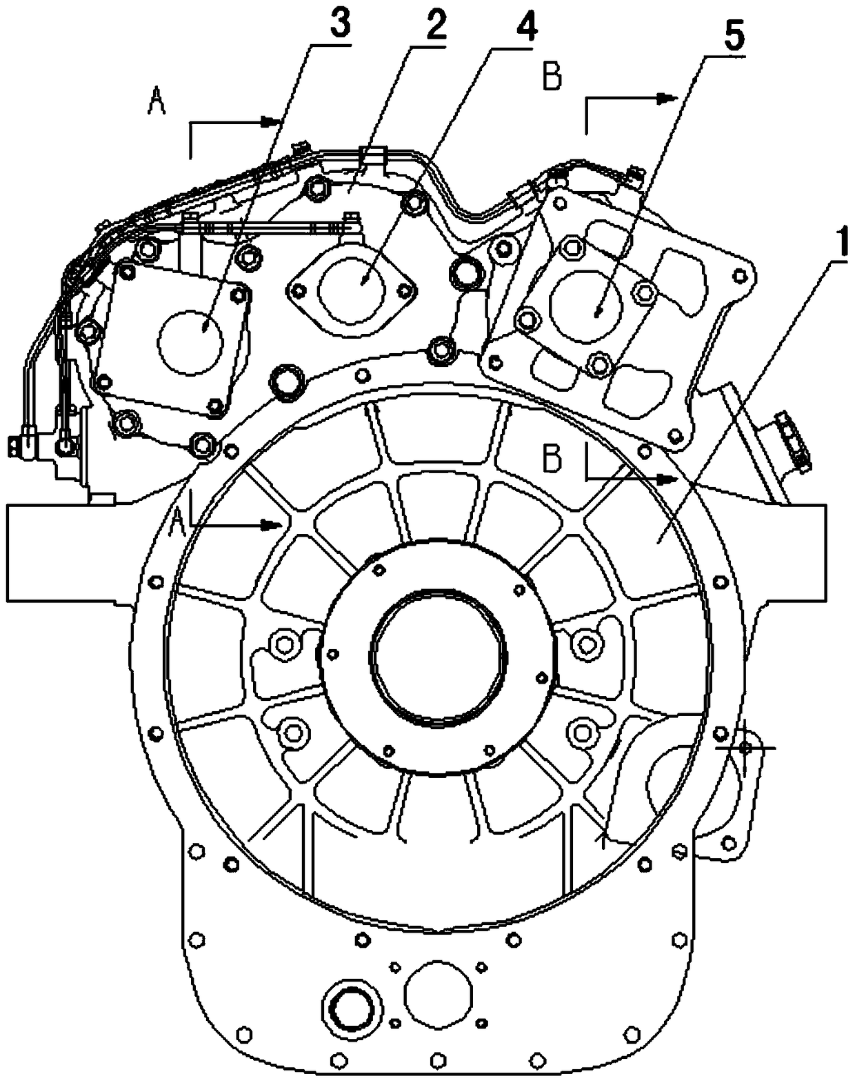
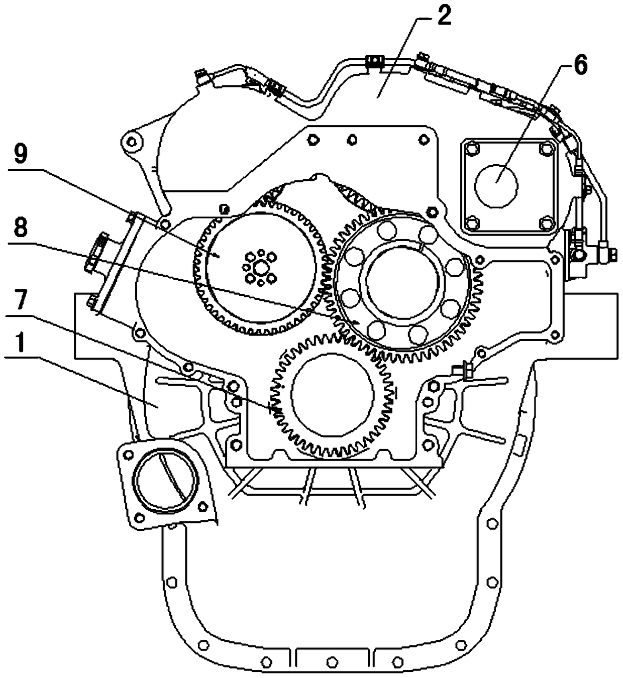
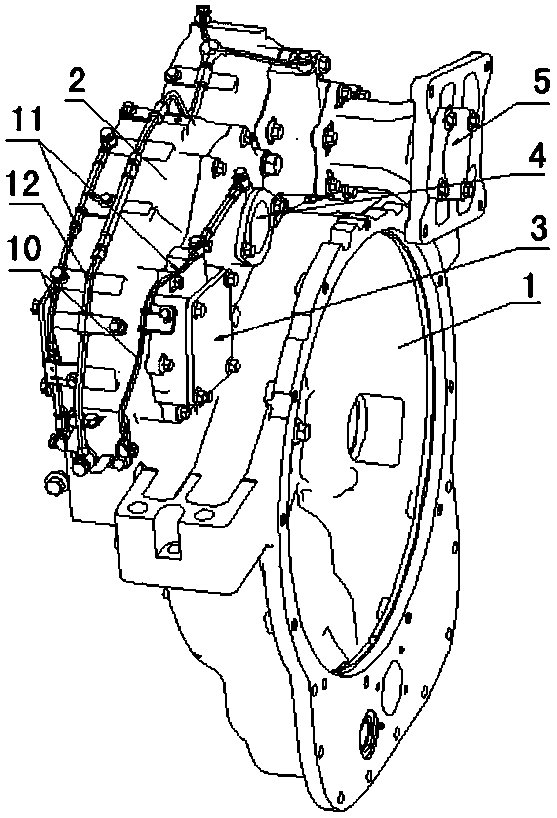
[0021] Figure 1 to Figure 5 It shows a structural schematic diagram of a multi-point power take-off structure of an engine according to a preferred embodiment of the present invention. like Figure 1 to Figure 3 As shown, the multi-point power take-off structure of the engine includes: flywheel housing 2, four PTO ports, four PTO shafts and lubricating pipes 10, 11, 12; flywheel housing 2 is arranged on the engine 1, and...


PUM


Abstract

The invention discloses an engine multipoint force taking structure, comprising a flywheel housing and four PTO shafts; the flywheel housing is arranged on an engine and is provided with four PTO ports including a first PTO port, a second PTO port, a third PTO port and a fourth PTO port; the four PTO shafts comprise a first PTO shaft, a second PTO shaft, a third PTO shaft and a fourth PTO shaft; the first PTO shaft and the fourth PTO shaft are coaxially arranged in the first PTO port and the fourth PTO port by rolling bearings; the second PTO shaft and the third PTO shaft are coaxially arranged in the second PTO port and the third PTO port by rolling bearings; the second PTO shaft is connected with a large idle gear of the engine by a gear; the third PTO shaft is connected with a cam shaft gear of the engine by a gear; the first PTO shaft is connected with a gear of the second PTO shaft by a gear. The structure can overcome the defect of poor structural adaptivity between a transfer case which is adopted as multiple power output ends of the engine and a postpositioned gear room engine.

Description

technical field [0001] The invention relates to the field of engines, in particular to an engine multi-point power take-off structure. Background technique [0002] Engine PTO is widely used in the fields of commercial vehicles and construction machinery. PTO (power take off, auxiliary power output) refers to the device that the engine outputs power to equipment other than the driving system of the car, such as the rotating mechanism of the transport tank of the concrete mixer truck, the lifting mechanism of the bulldozer blade, hydraulic transmission, steering mechanism, etc. Both require PTO power. Generally, engines have only one PTO output port, but construction machinery such as bulldozers require 3 to 4 PTO power take-off ports. Therefore, general vehicle manufacturers need to make a special transfer case structure to meet the multi-point PTO output. Demand, and the transfer case is installed to the rear end of the engine by the OEM when the engine is installed in th...

Claims


Application Information

Patent Timeline
Patent Type & Authority Patents(China)
IPC IPC(8): F16H1/22F16H57/04F16M1/026F02B61/06F01M9/12
CPCF01M9/12F02B61/06F16H1/22F16H57/0412F16H57/0471F16M1/026
Inventor 秦江福谭贵荣刘治春秦儒宏刘蓉
Owner GUANGXI YUCHAI MASCH CO LTD
Learn More