
Insert structure for injection moulding

A technology of injection molding and inserts, applied in the direction of coating, etc., can solve the problems of affecting product appearance, injection molding defects, cracks, etc., and achieve the effect of improving injection molding defects, increasing production competitiveness, and expanding filling space

Active Publication Date: 2016-04-20
SHENZHEN SUNWAY COMM
View PDF4 Cites 3 Cited by
  • Summary
  • Abstract
  • Description
  • Claims
  • Application Information

AI Technical Summary

Problems solved by technology

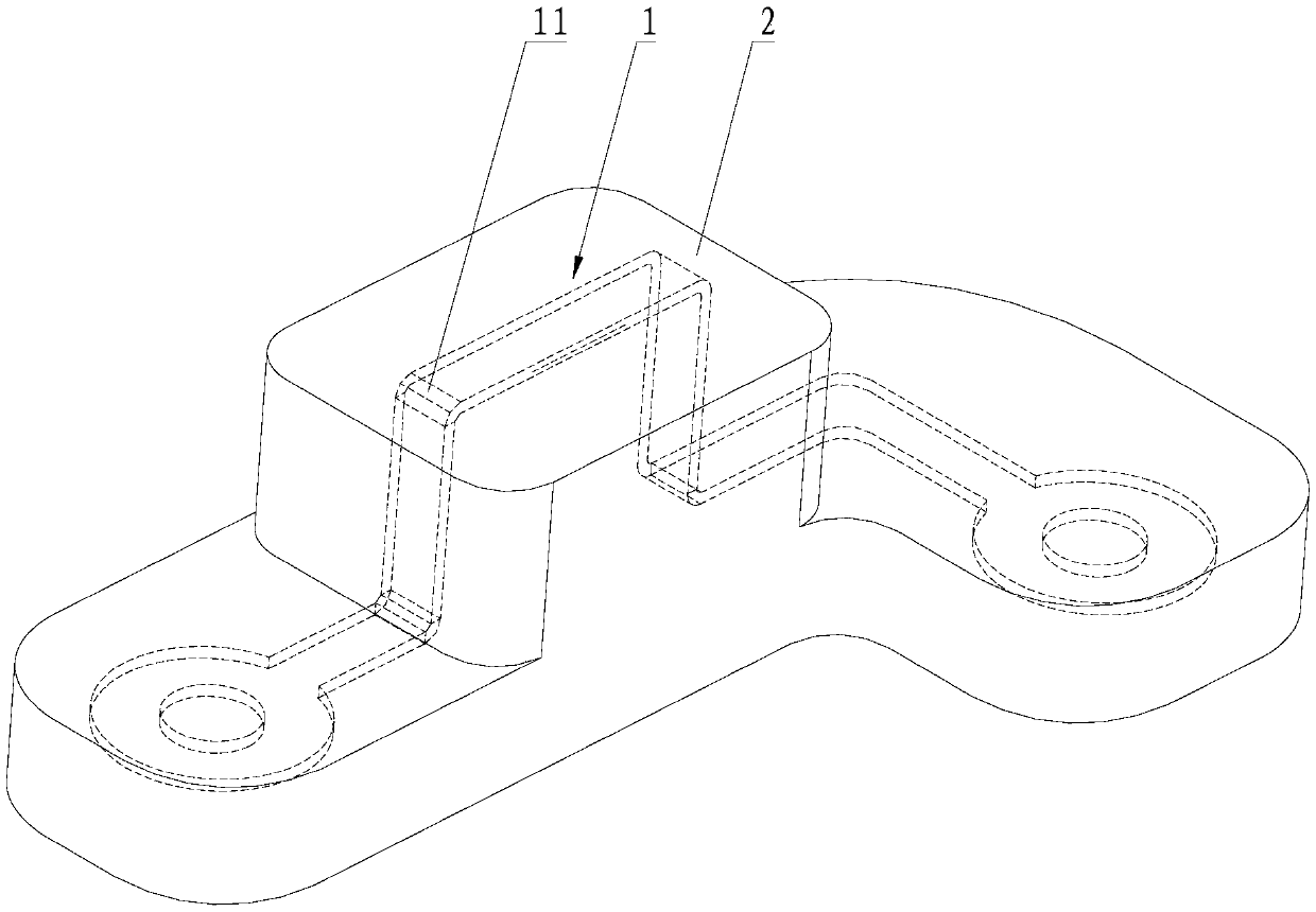
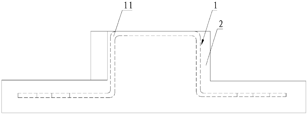
[0003] like figure 1 and figure 2 As shown, when the insert body 1 has many bends and is embedded on the surface of the product, the intersection of the bent part 11 of the insert body 1 and the plastic 2 will form an acute-angle area, which makes it difficult to fill the acute-angle area during injection molding, thus The lack of plastic defects in injection molding not only affects the appearance of the product, but also causes cracks due to the release of the internal stress of the plastic during the cold cycle test of the product, which reduces the yield of the product and increases the cost
For example, the patent document with application number 201410737149.8 discloses a ring-shaped insert molded product. The parts made of steel plate, the junction of the cylindrical part and the ring part is the bending area. During injection molding, the bending area is likely to cause plastic shortage in the injection molding, thus affecting the appearance and performance of the product

Method used


Image

  • Insert structure for injection moulding
  • Insert structure for injection moulding
  • Insert structure for injection moulding

Examples


Embodiment 1

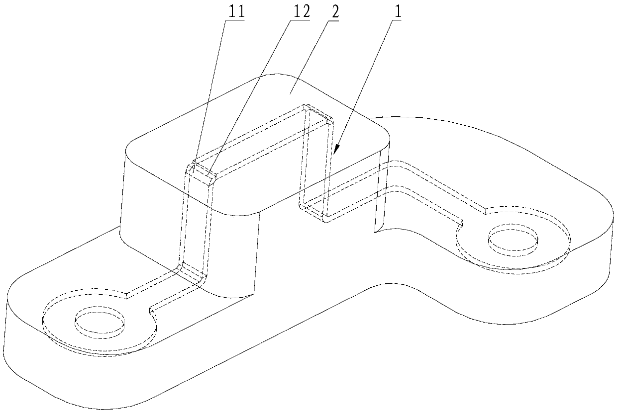
[0035] Please refer to image 3 with Figure 4 , The first embodiment of the present invention is:

[0036] An insert structure for injection molding includes an insert body 1, a bending portion 11 is provided on the insert body 1, and a step portion 12 is provided on the bending portion 11.

[0037] The bent portion 11 includes a first straight portion and a second straight portion, the first straight portion is connected to the second straight portion, the angle formed by the connection between the first straight portion and the second straight portion is not equal to 180°, and the stepped portion 12 It is arranged at the joint, the number of the stepped portion 12 is two, and the two stepped portions 12 are respectively located at the edge position of the first straight portion and arranged along the width direction of the first straight portion. The provision of two stepped portions 12 can not only increase the filling area of ​​the plastic 2, but also ensure the thickness h2 ...

Embodiment 2

[0042] For an insert structure for injection molding, see Embodiment 1. The difference between the insert structure for injection molding in this embodiment and Embodiment 1 is:

[0043] The depth h1 of the step portion is 0.47-0.49 of the thickness h2 of the bent portion on the insert body 1. When the depth h1 of the step portion is 0.47-0.49 of the thickness h2 of the bending portion, there is still enough space between the insert and the mold to completely fill the plastic 2 to avoid injection defects, and to further increase the insert The strength of the product increases the service life of the product.

[0044] In summary, an insert structure for injection molding provided by the present invention can not only avoid injection molding defects, but also eliminates the need to modify the injection molding mold, which can improve such injection molding defects at a lower cost and increase Improve the production competitiveness of enterprises.


PUM


Abstract

The invention discloses an insert structure for injection moulding. The insert structure comprises an insert body. A bent part is arranged on the insert body. A step part is arranged on the bent part. According to the insert structure for injection moulding, the defects of injection moulding can be avoided, it is unnecessary to modify an injection moulding mould, the defects of injection moulding can be overcome with the low cost, and production competitiveness of enterprises is improved.

Description

Technical field [0001] The invention relates to the technical field of insert injection molding, in particular to an insert structure for injection molding. Background technique [0002] Insert injection molding refers to a molding method in which pre-prepared inserts of dissimilar materials are injected into the mold, and the molten plastic is joined and solidified with the dissimilar materials to form an integrated product. In the process of insert injection molding, the shape of the insert has a great influence on injection molding. [0003] Such as figure 1 with figure 2 As shown, when the insert body 1 has more bends and is embedded on the surface of the product, the intersection of the bent portion 11 of the insert body 1 and the plastic 2 will form an acute-angled area, which makes it difficult to fill the acute-angled area during injection molding. The defect caused by the lack of plastic injection not only affects the appearance of the product, but also during the cold c...

Claims


Application Information

Patent Timeline
Patent Type & Authority Applications(China)
IPC IPC(8): B29C45/14
CPCB29C45/14819
Inventor 刘序俊
Owner SHENZHEN SUNWAY COMM
Learn More