Rapid mold changing mechanism of tire

A fast, tire technology, applied in tires, other household appliances, household appliances, etc., can solve the problems of potential safety hazards, low mold replacement efficiency, and high risk

Active Publication Date: 2016-04-20
SAFE RUN & HISCENT MACHINERY SUZHOU
View PDF4 Cites 0 Cited by
  • Summary
  • Abstract
  • Description
  • Claims
  • Application Information

AI Technical Summary

Problems solved by technology

[0002] At present, in the hydraulic vulcanizing machine used in the tire factory, it is necessary to replace the mold when making tires of different specifications. Every time the mold is replaced, it is necessary to manually install the bolts for fixing the mold on the high-temperature vulcanization chamber. The mold efficiency is low, the risk is high, and there are potential safety hazards, and the manual operation cannot guarantee the fixed accuracy

Method used


Image

  • Rapid mold changing mechanism of tire
  • Rapid mold changing mechanism of tire
  • Rapid mold changing mechanism of tire

Examples


Embodiment Construction

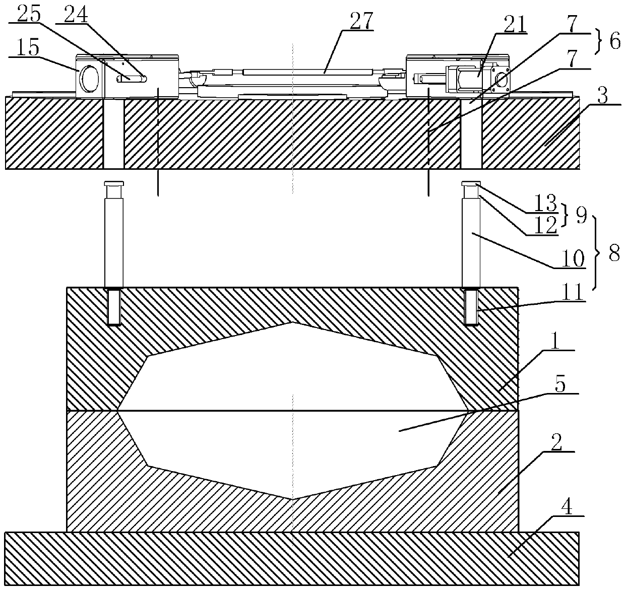
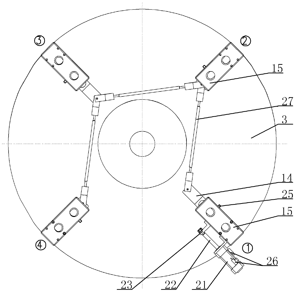
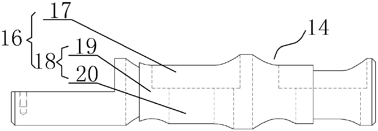
[0020] A kind of quick mold change mechanism of tire, see Figure 1 to Figure 5 : It includes an upper mold 1, a lower mold 2, an upper pallet 3, a lower pallet 4, the upper mold 1 and the lower mold 2 are combined to form a cavity 5, and the upper mold 1 and the lower mold 2 in the working state are located on the upper pallet 3 , between the lower supporting plates 4, the upper supporting plate 3 can move vertically up and down, and the upper supporting plate 3 is provided with N groups of vertically penetrating guide hole groups 6, and each group of guide hole groups 6 includes at least one guide hole 7, wherein N is a natural number ≥ 2. The upper end surface of the upper mold 1 is fixed with N clamping bolts 8. The clamping bolts 8 are exposed on the upper end surface of the upper mold 1. The clamping bolts 8 specifically include the top clamping part 9, the middle The connecting part 10, the bottom fastening thread part 11, the bottom fastening thread part 11 of the clam...


PUM


Abstract

The invention provides a rapid mold changing mechanism of a tire. The rapid mold changing mechanism improves the mold changing efficiency of a tire factory, lowers the labor intensity of operators, reduces working risks, and ensures stability. The rapid mold changing mechanism comprises an upper mold, a lower mold, an upper supporting plate and a lower supporting plate. The upper mold and the lower mold are combined to form a cavity. The upper mold and the lower mold are located between the upper supporting plate and the lower supporting when in the working state. The upper supporting plate can move up and down in the perpendicular direction. The rapid mold changing mechanism is characterized in that the upper supporting plate is provided with N guide hole sets penetrating through the upper supporting plate in the perpendicular direction. Each guide hole set comprises at least one guide hole, wherein N is a natural number larger than or equal to 2. N mold locking bolts are fixedly arranged on the upper end face of the upper mold and exposed out of the upper end face of the upper mold. Each mold locking bolt specifically comprises a top mold locking portion, a middle connecting portion and a bottom fastening thread portion, wherein the bottom fastening thread portion of the mold locking bolt is fixedly arranged inside a corresponding positioning hole in the upper mold.

Description

technical field [0001] The invention relates to the technical field of tire equipment, in particular to a quick mold change mechanism for tires. Background technique [0002] At present, in the hydraulic vulcanizing machine used in the tire factory, it is necessary to replace the mold when making tires of different specifications. Every time the mold is replaced, it is necessary to manually install the bolts for fixing the mold on the high-temperature vulcanization chamber. The mold efficiency is low, the risk is high, and there are potential safety hazards, and manual operation cannot guarantee the accuracy of the fixation. Contents of the invention [0003] In view of the above problems, the present invention provides a quick mold change mechanism for tires, which improves the efficiency of mold change in tire factories, reduces the labor intensity of operators, reduces work risks, and ensures stability. [0004] A quick mold change mechanism for tires, the technical so...

Claims


Application Information

Patent Timeline
IPC IPC(8): B29C33/30B29D30/06
CPCB29C33/30B29C33/305B29D30/0606B29D2030/0607
Inventor 熊远林杨建斌
Owner SAFE RUN & HISCENT MACHINERY SUZHOU
Why Eureka
Try Eureka