Ion chamber radiation detector

A technology of radiation detectors and ionization chambers, which is applied in radiation measurement, neutron radiation measurement, instruments, etc., and can solve the problems that the movable detector does not meet the performance characteristics and increases the operating cost of the detector system, etc.

Active Publication Date: 2016-04-13
WESTINGHOUSE ELECTRIC CORP
View PDF12 Cites 3 Cited by
  • Summary
  • Abstract
  • Description
  • Claims
  • Application Information

AI Technical Summary

Problems solved by technology

[0009] Each type of movable detector has sub-optimal performance characteristics that significantly increase the operating cost of the detector system

Method used


Image

  • Ion chamber radiation detector
  • Ion chamber radiation detector
  • Ion chamber radiation detector

Examples


Embodiment Construction

[0021] The primary side of a nuclear power generation system cooled with pressurized water includes a closed circuit that is isolated and in heat exchange relationship with a secondary side for generating useful energy. The primary side consists of the reactor vessel (which encloses the core internal structure that supports multiple fuel assemblies containing fissile material), the primary loop in the heat exchange steam generator, the internal volume of the pressurizer, the Pumps and piping for pressurized water; piping connects each of the steam generators and pumps independently to the reactor vessel. Parts of the primary side include steam generators, pumps and piping connected to the vessel forming a primary side circuit.

[0022] For purposes of illustration, FIG. 3 shows a simplified nuclear reactor primary system including a generally cylindrical reactor pressure vessel 52 having a head 68 enclosing the nuclear core 54 . Liquid reactor coolant, such as water, is pumpe...


PUM


Abstract

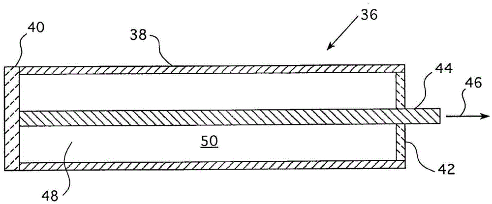
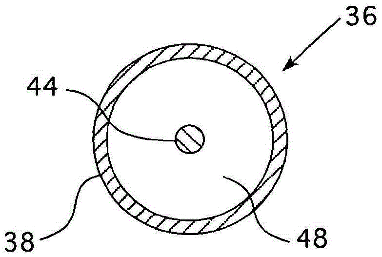
An in-core nuclear detector for detecting the neutron population surrounding the detector. The detector is an ion chamber having a cylindrical outer electrode that is insulated from a central electrode and capped to contain an Argon gas. An electron radiator that produces prompt neutron capture gamma radiation that is substantially, directly proportional to the local neutron population is disposed between the outer tubular electrode and the central electrode.

Description

technical field [0001] The present invention relates generally to apparatus for monitoring power distribution within the core of a nuclear reactor, and more particularly to ionization chamber detectors with enhanced fission gamma radiation response. Background technique [0002] In many older reactors currently in operation relying on nuclear flux measurements such as those used in reactor control and protection systems, excore detectors supplemented by incore flux mapping systems are provided as early as 1967 It has been in use since 2010; the in-core flux mapping system was originally intended to provide evidence of the core design and some calibration measurements. [0003] With the growing trend towards larger reactor cores, there has been some concern about possible adverse effects on core power distribution and the ability of excore detectors to adequately detect this possible adverse power distribution. Test data show that currently used split-section excore detector...

Claims


Application Information

Patent Timeline
Patent Type & Authority Applications(China)
IPC IPC(8): G21C17/06
CPCG01T3/008G21C17/108H01J47/1233Y02E30/30
Inventor M·D·海贝尔
Owner WESTINGHOUSE ELECTRIC CORP
Why Eureka
Try Eureka