
Rotary hoisting equipment for stiffening beam of suspension bridge and erecting method of stiffening beam

A technology for hoisting equipment and stiffening beams, which is applied in the field of rotating hoisting equipment for stiffening beams of suspension bridges and the erection of stiffening beams, and can solve problems such as uneconomical, difficult construction of cable crane frames, poor safety and reliability, etc.

Inactive Publication Date: 2016-04-13
CHANGAN UNIV +2
View PDF5 Cites 5 Cited by
  • Summary
  • Abstract
  • Description
  • Claims
  • Application Information

AI Technical Summary

Problems solved by technology

[0005] With the rapid development of our country's economy, more and more highways and cross-sea and island-connecting projects have been built, and the projects of building long-span suspension bridges on valleys, deep ditches, rapid rivers, high-wave seas and busy waterways have gradually increased. When hoisting the stiffening girder of the suspension bridge under the above working conditions, the method of spanning the cable crane frame is no longer applicable, and the method of the cable crane frame also has the disadvantages of difficult construction, poor safety and reliability, and uneconomical. Therefore, it is urgent to study a Economical and practical hoisting equipment and corresponding hoisting methods suitable for the erection of stiffened beams of suspension bridges with low construction difficulty, high safety and reliability

Method used


Image

  • Rotary hoisting equipment for stiffening beam of suspension bridge and erecting method of stiffening beam
  • Rotary hoisting equipment for stiffening beam of suspension bridge and erecting method of stiffening beam
  • Rotary hoisting equipment for stiffening beam of suspension bridge and erecting method of stiffening beam

Examples


Embodiment 1

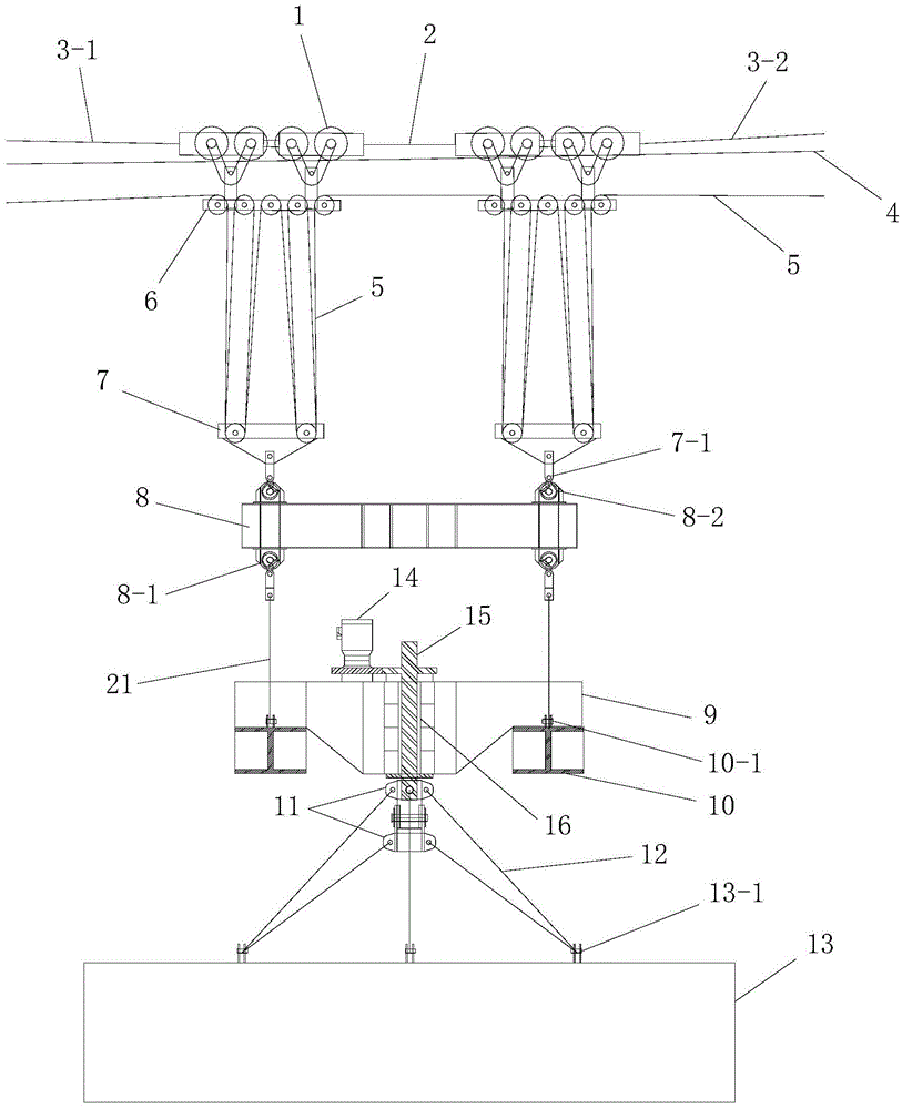
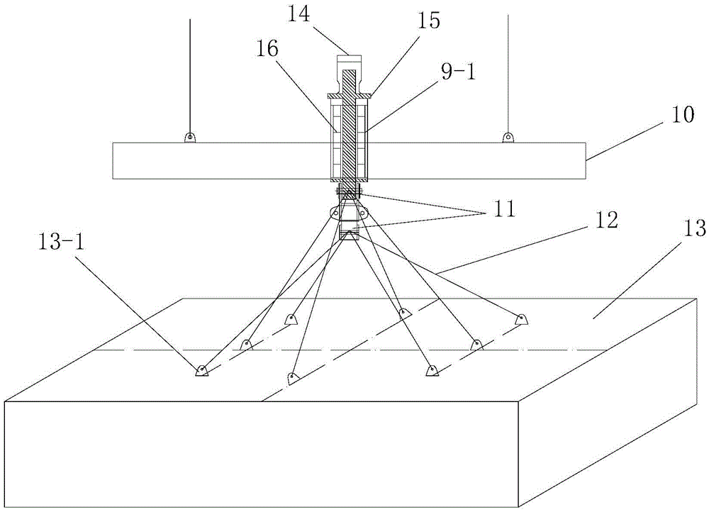
[0065] Such as figure 1A suspension bridge stiffening beam rotating hoisting equipment shown, including hoisting the stiffening beam section 13 and rotating the hoisting stiffening beam section 13 horizontally rotating sling 9, and a pole beam 8 located directly above the slinging sling 9 And the hoisting mechanism that hoists the rotating hoist 9 through the shoulder pole beam 8 and can move forward and backward along the longitudinal bridge direction. The hanger 9 is hoisted on the shoulder pole beam 8 and it is located directly below the shoulder pole beam 8, and the shoulder pole beam 8 is hoisted on the lifting mechanism and it is located below the lifting mechanism. The hoisting mechanism is installed on the cable tower 20 of the suspension bridge under construction; the rotating sling 9 includes a hoisting frame, a vertical shaft installed on the hoisting frame, and a rotary drive mechanism that drives the vertical shaft to rotate horizontally , the stiffening beam sec...

Embodiment 2

[0127] In this embodiment, the structure and connection relationship of the suspension bridge stiffening beam rotary hoisting equipment used are the same as those in Embodiment 1.

[0128] In this embodiment, the suspension bridge stiffening beam erection method adopted is different from Embodiment 1 in that: in step one, the front side beam body is erected, and in step four, the rear side beam body 24 is erected; When installing the hoisting balance mechanism in step 2, a balance cable hoist 18 is installed at the front end of the front side beam body; when erecting the middle beam body in step 3, multiple stiffening beam sections 13 Carry out erection respectively, the erection method of a plurality of described stiffening beam sections 13 is all the same; When any one described stiffening beam section 13 is erected, the process is as follows:

[0129] Step 301, longitudinal translation of the beam section: use the beam transport trolley 19 to translate the currently erected...


PUM


Abstract

The invention discloses rotary hoisting equipment for a stiffening beam of a suspension bridge and an erecting method of the stiffening beam. The rotary hoisting equipment comprises rotary slings, balance beams and a hoisting mechanism, wherein the rotary slings are used for hoisting stiffening beam segments and enabling the hoisted stiffening beam segments to horizontally rotate; the balance beams are positioned right above the rotary slings; the hoisting mechanism is used for hoisting the rotary slings through the balance beams and can move forwards and backwards in the direction longitudinal to the bridge; the stiffening beam segments are hoisted on the rotary slings, the rotary slings are hoisted on the balance beams, and the balance beams are hoisted on the hoisting mechanism and are positioned under the hoisting mechanism; the hoisting mechanism is mounted on cable bent towers of the constructed suspension bridge. The erecting method of the stiffening beam comprises the following steps of: I, erecting a rear-side beam body or a front-side beam body; II, mounting a hoisting balance mechanism; III, erecting a middle beam body; and IV, erecting the front-side beam body or the rear-side beam body. According to the rotary hoisting equipment for the stiffening beam of the suspension bridge and the erecting method of the stiffening beam, disclosed by the invention, the design is reasonable, the realization is convenient, the use effects are good, the construction difficulty is low, and the hoisting and erecting process of the stiffening beam of the suspension bridge can be simply and rapidly completed.

Description

technical field [0001] The invention belongs to the technical field of bridge construction, and in particular relates to a suspension bridge stiffening girder rotary hoisting device and a stiffening girder erection method. Background technique [0002] Suspension bridge, also known as suspension bridge, refers to a bridge with cables (or steel chains) suspended by towers and anchored on both banks (or both ends of the bridge) as the main load-bearing components of the upper structure. In order to avoid the deformation of the bridge deck along with the suspension cables during the running of vehicles, modern suspension bridges are generally equipped with rigid girders (also known as stiffening girders). The stiffening beam of the suspension bridge mainly plays the role of supporting and transmitting the load, and is the main component bearing the wind load and other transverse horizontal forces. Most of the stiffened girders of long-span suspension bridges use steel structur...

Claims


Application Information

Patent Timeline
Patent Type & Authority Applications(China)
IPC IPC(8): E01D21/08
CPCE01D21/08
Inventor 刘来君夏国邦陈永瑞周罡段妙奇武芳文李培峰张柳煜张水华张筱雨陈辅一
Owner CHANGAN UNIV
Learn More