Improved sludge treatment system

A sludge treatment and sludge technology, applied in sludge treatment, water/sludge/sewage treatment, sludge treatment by temperature control, etc., can solve the problems of low drying efficiency, complex structure and poor drying effect.

Inactive Publication Date: 2016-04-13
王良源
View PDF7 Cites 0 Cited by
  • Summary
  • Abstract
  • Description
  • Claims
  • Application Information

AI Technical Summary

Problems solved by technology

[0006] Therefore, the technical problem to be solved by the present invention is to overcome the defects of low drying efficiency, poor drying effect and complex structure of the drying system in the treatment of solid-liquid mixture (such as sludge) in the prior art, thereby providing a method that can improve drying efficiency. , Sludge treatment system with simple structure and improved drying effect

Method used


Image

  • Improved sludge treatment system
  • Improved sludge treatment system
  • Improved sludge treatment system

Examples


Embodiment 1

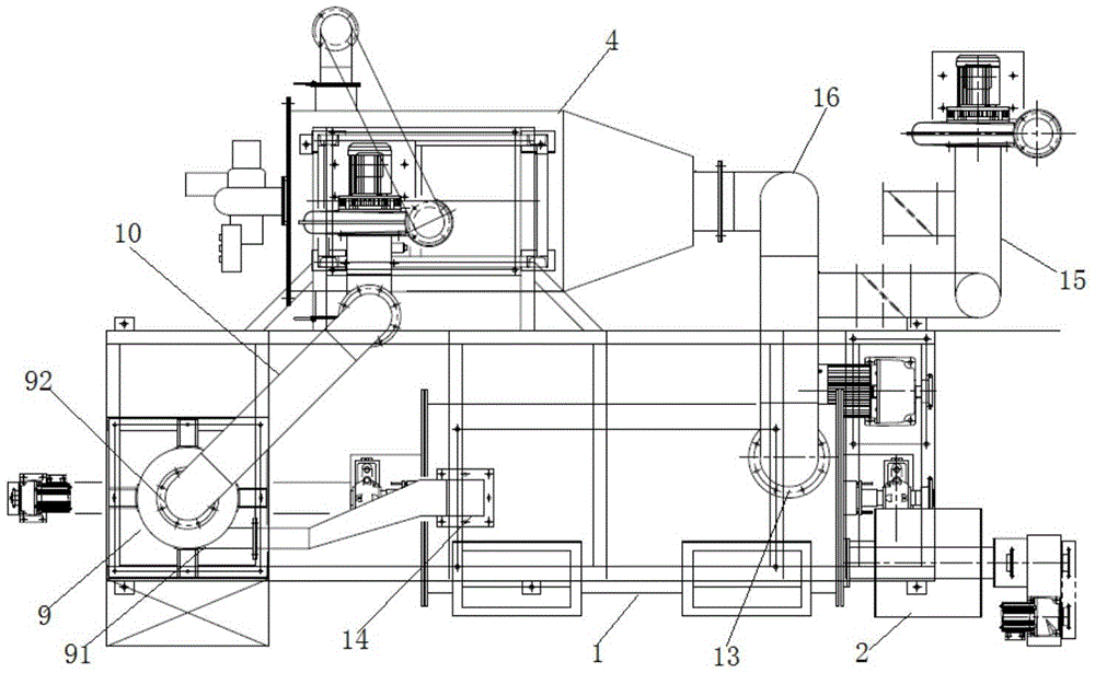
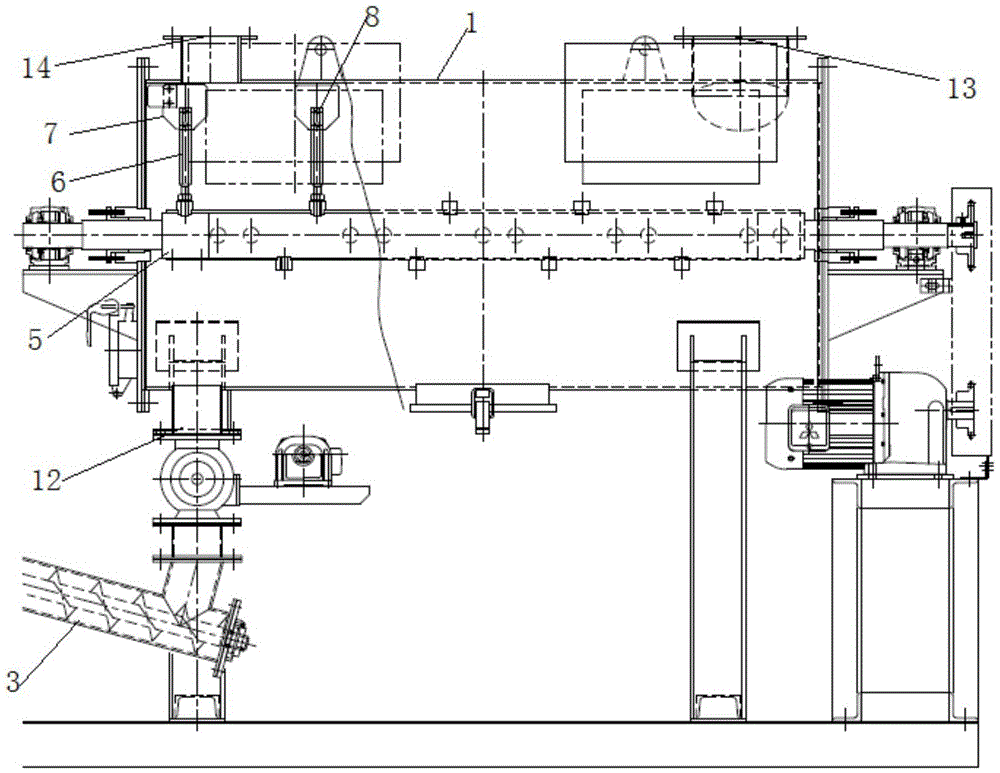
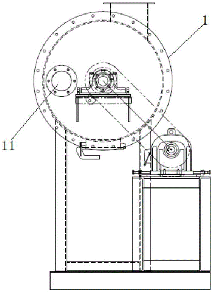
[0042] Such as Figure 5 As shown, this embodiment provides an improved sludge treatment system, including

[0043] The transmission device has a two-stage transmission surface, the first-stage transmission surface is located above the side of the second-stage transmission surface, the first-stage transmission surface 200 and the second-stage transmission surface 300 are connected by a transition device 500, and the first-stage transmission surface The height between 200 and the second-stage transmission surface 300 is greater than 100cm, and the transmission device can transport the solid-liquid mixed sludge from the head end of the first-stage transmission surface to the tail end of the first-stage transmission surface, and through the transition The device 500 is introduced to the second-level transmission surface, and transported from the head end of the second-level transmission surface to the tail end of the second-level transmission surface;

[0044] The dewatering str...


PUM


Abstract

The invention relates to an improved sludge treatment system which comprises a transmission device, a water removal structure and a drying device. The drying device comprises a furnace body, a feed device for adding materials into the furnace body, a material collecting device for collecting the dried materials in the furnace body, an air supply device leading external hot gas into the furnace body through a first gas inlet, and a stirring device for stirring and smashing the materials. The stirring device comprises a second rotary shaft which is arranged in a cavity of the furnace body in a penetrating mode. The second rotary shaft is provided with a ventilating cavity. A plurality of gas spraying openings are formed in the ventilating cavity. The gas spraying direction of the gas spraying openings, the stirring direction of a stirring shaft and the stirring direction of blades are neither overlapped nor parallel. When the materials are dried, hot gas is led into the cavity of the furnace body through the first gas inlet, the second rotating shaft rotates to drive a stirring assembly on the second rotating shaft so that the materials can be continuously stirred in the radial and axial directions of the second rotating shaft and can roll in the axial and radial directions of the second rotating shaft in the furnace body.

Description

technical field [0001] The invention relates to the technical field of sludge treatment, in particular to an improved sludge treatment system. Background technique [0002] Sludge is the product of the sewage treatment process, which contains a large amount of organic matter, heavy metals and molds, etc. If no follow-up treatment is added, it will cause serious pollution to the environment. Therefore, it is often necessary to concentrate and dehydrate the sludge, but after this treatment The moisture content of the final sludge is usually above 70%, and the sludge needs to be further dried. [0003] In the prior art, the drying system used for sludge drying is mostly structured as the drying system disclosed in the Chinese patent document CN201058838Y, including a furnace body, a feeder connected to the feed port of the furnace body, and an air outlet of the furnace body. Connected spray tower. Among them, the furnace body includes a transmission shaft arranged in the furn...

Claims


Application Information

Patent Timeline
IPC IPC(8): C02F11/12C02F11/18
CPCC02F11/12C02F11/121
Inventor 王良源
Owner 王良源
Why Eureka
Try Eureka