
Wind turbine blade with sections that are joined together

A technology of wind turbine blades and blades, which is applied in the field of segmented blades, can solve the problems of blade rigidity and weight considerations, and achieve the effects of increased strength, simple forming, and simple combination

Active Publication Date: 2016-04-06
VESTAS WIND SYST AS
View PDF5 Cites 15 Cited by
  • Summary
  • Abstract
  • Description
  • Claims
  • Application Information

AI Technical Summary

Problems solved by technology

[0008] Wind turbine blades manufactured in parts or sections for later joining are known, however the main problem is to obtain the necessary strength of the joints between the joined blade parts and the safe transfer of loads and moments across the joints
Furthermore, difficulties may arise in designing and fabricating blade joints without compromising blade stiffness and weight considerations

Method used


Image

  • Wind turbine blade with sections that are joined together
  • Wind turbine blade with sections that are joined together
  • Wind turbine blade with sections that are joined together

Examples


Embodiment Construction

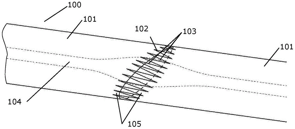
[0059] figure 1 A portion of a wind turbine blade 100 comprising two blade segments 101 joined at a blade joint 102 is shown. Each blade segment 101 includes at its connecting end 105 a plurality of prongs or fingers 103 interconnected across a joint 102 . The spar cap structure 104 of each blade segment is indicated by hatching. The spar cap structure may advantageously increase in size towards the blade joint 102 to increase the strength of the joint and the strength of the blade itself across the joint. In the illustrated embodiment, tooth-like protrusions are formed throughout the blade shell. In other embodiments, the serrations are formed in only a portion of each blade segment connection end, such as in a spar cap structure.

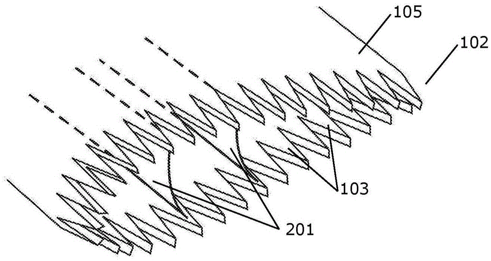
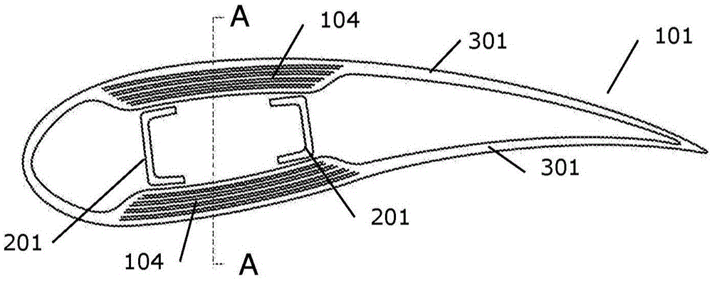
[0060] figure 2 The disassembled joint 102 is shown with serrations 103 formed in the blade segment connection ends 105 . Here, the serrations are formed in the shell structure comprised in the spar cap structure 104 of both the leeward and ...


PUM


Abstract

A wind turbine blade comprising at least two wind turbine blade sections connected in a blade connection joint, where each blade section at their connection end comprises a number of corresponding dentations arranged to interconnect across the blade connection joint. One of the blade sections comprises a spar cap structure and a connecting part with a first end joined to the spar cap structure and an opposite second end positioned at the blade section connection end and comprising a number of the dentations. The connecting part further comprises a number of sheets which are interleaved with the fibre-reinforced layers of the spar cap structure in an overlapping zone thereby joining the spar cap structure and the connecting part. The invention further relates to a method for preparing a wind turbine blade section as mentioned above. The invention also relates to a method of preparing a sheet for a connecting part with a number of dentations at one end, which method involves cutting and rolling a number of unidirectional prepreg sheets to form fingers, placing in an open mould the fingers next to each other and partially apart such as to form the dentations, closing the mould, and fully or partially curing the sheet.

Description

technical field [0001] The invention relates to a segmented blade for a wind turbine comprising at least a first blade segment and a second blade segment extending in opposite directions from a blade joint And structurally connected by spar bridges. Background technique [0002] A modern wind turbine comprises a plurality of wind turbine rotor blades, usually three blades, each weighing up to 35 tons and up to 55 meters long. [0003] Traditionally, a blade comprises two shell parts, one shell part defining the windward side shell part and the other shell part defining the leeward side shell part. Each housing part is conventionally made in one piece. [0004] In one type of blade sometimes referred to as a structural shell blade, the blade is stiffened by individual shell components including one or more spar caps that act as stiffening spars extending longitudinally in each shell. Additionally, a plurality of webs are located in the cavity between two wind turbine shell...

Claims


Application Information

Patent Timeline
Patent Type & Authority Applications(China)
IPC IPC(8): F03D1/06
CPCF03D1/065F03D1/0675F05B2220/30F05B2230/20F05B2240/302F05B2260/30F05B2280/6003Y02E10/72Y02P70/50
Inventor 安东·贝什P·希巴德
Owner VESTAS WIND SYST AS
Learn More