Cooperative transmission method suitable for distributed antenna system, base station and terminal
A distributed antenna and cooperative transmission technology, applied in diversity/multi-antenna systems, radio transmission systems, transmission systems, etc., can solve problems such as excessive reception time difference, imperfect backbone network devices, and reduced system spectral efficiency, etc. Effective transmission rate, the effect of solving the problem of asynchronous signal arrival
- Summary
- Abstract
- Description
- Claims
- Application Information
AI Technical Summary
Problems solved by technology
Method used
Image


Examples
Embodiment 1
[0091] Embodiment 1: This embodiment describes a wireless communication system using a shaping filter bank based multi-carrier (FBMC) modulation technique.
[0092] Table 1
[0093] System bandwidth (System bandwidth (MHz))
250
Sampling rate (Sampling rate (MHz))
276.48
Carrier spacing (Subcarrier spacing (kHz))
270
OFDM symbol length (OFDM symbol length (FFT size))
1024
OFDM symbol duration (OFDM symbol duration(us))
3.70
CP length (CP length)
128
CP duration (CP duration(us))
0.46
[0094] In this embodiment, a specific implementation of a wireless communication system based on a shaping filter bank multi-carrier modulation technology is given. For the convenience of understanding, the system is compared with a traditional OFDM system: assuming that the parameters of the OFDM system are shown in Table 1, an OFDM time domain signal can be generated by formula (1):
[0095] s ...
Embodiment 2
[0106] Embodiment 2: This embodiment describes an active cooperative transmission method of a multi-antenna system.
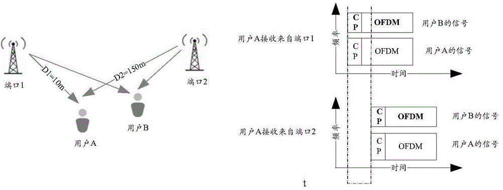
[0107] first, image 3 A distributed antenna system based on OFDM modulation is shown. The network transmits data of two users at the same time through two antennas 1 and 2, and through an Orthogonal Frequency Division Multiplexing (OFDMA) method. Due to the distance difference between the user and the antenna, the two signals (from antenna 1 and 2) received by the user (for example, user A) have a time difference at the receiving end, which is called a delay difference in this application. For example, the distribution of users and antennas is as follows image 3 As shown, the delay difference at user A is τ=(D2-D1) / 3*10 8 =0.46us, where, 3*10 8 m / s is the speed of light. If the parameters used by the system are shown in Table 1, it can be seen that the delay difference has exceeded the length of the CP, and the received signal is as follows image 3 sho...
Embodiment 3
[0110] Embodiment 3: This embodiment describes the measurement, feedback and adjustment of the antenna time delay.
[0111] In the second embodiment, the active cooperative transmission method adjusts the transmission time of the antennas or adjusts the parameters of the modulation waveform according to the delay of each antenna reaching the user. This requires the network to be able to obtain the delay difference between each antenna and the user first. Obtaining the delay difference can be achieved through various methods. This embodiment introduces a method through user measurement and feedback:
[0112] The network allocates an independent reference signal for each antenna, such as the CSI-RS reference signal in the LTE system. The reference signal is sent using a user-independent reference time, so the user can always obtain the transmission delay of the corresponding antenna by measuring the reference signal. A set of delay difference thresholds is predefined. When the...
PUM
 Abstract
Description
Claims
Application Information
 - Generate Ideas
- Intellectual Property
- Life Sciences
- Materials
- Tech Scout
- Unparalleled Data Quality
- Higher Quality Content
- 60% Fewer Hallucinations
Browse by: Latest US Patents, China's latest patents, Technical Efficacy Thesaurus, Application Domain, Technology Topic, Popular Technical Reports.
© 2025 PatSnap. All rights reserved.Legal|Privacy policy|Modern Slavery Act Transparency Statement|Sitemap|About US| Contact US: help@patsnap.com