Mobile power distribution network intelligent integrated power supply vehicle
What is Al technical title?
Al technical title is built by PatSnap Al team. It summarizes the technical point description of the patent document.
A power supply vehicle, mobile technology, applied in the direction of electrical components, switchgear, etc.
Active Publication Date: 2016-04-06
国网山东阳谷县供电公司
View PDF8 Cites 4 Cited by
Summary
Abstract
Description
Claims
Application Information
AI Technical Summary
This helps you quickly interpret patents by identifying the three key elements:
Problems solved by technology
Method used
Benefits of technology
Problems solved by technology
[0003] The main purpose of the present invention is to overcome the need for power outages in the maintenance and replacement of the original transformer failure, large power outage range, long time or high cost Only with the cooperation of special vehicles can the replacement of transformers be realized and the maintenance cost of power supply is relatively high.
Provide a mobile distribution network intelligent integrated power supply vehicle, which can realize the replacement or maintenance of transformers and down-conductor equipment without power failure, which overcomes the traditional replacement or maintenance of transformers that must be powered off or requires the cooperation of several special operating vehicles. Completed work, thus solving the economic losses caused by the power supply companies needing a large amount of money to purchase multiple vehicles, the inconvenience caused to residents' daily electricity use and the cumbersome operation of multiple vehicles
Method used
Image
Click on the blue label to locate the original text in one second.
Reading with bidirectional positioning of images and text.
Examples
Embodiment Construction
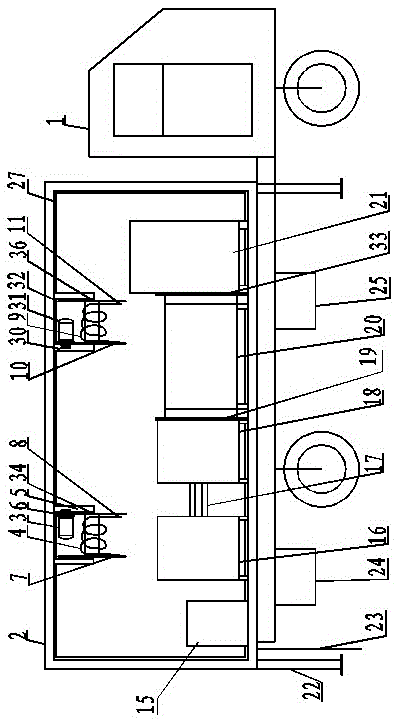
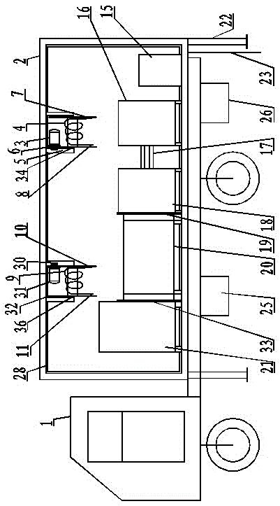
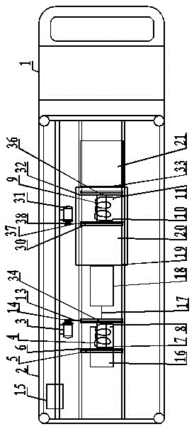
[0018] Such as figure 1 , figure 2 , image 3 , Figure 4As shown, the mobile distribution network intelligent integrated power supply vehicle is mainly composed of a second-class automobile chassis 1, a compartment body 2, a power control device 15, a high-voltage automatic cable reel device, a low-voltage automatic cable reel device, an explosion-proof transformer 20, an explosion-proof Type high-voltage switchgear 21, explosion-proof low-voltage switchgear 18, low-voltage GP cabinet 16, tool box 25, power generation device 26, hydraulic outrigger control device 24, hydraulic grounding device 23; explosion-proof transformer 20 is installed in the car body 2 In the middle of the bottom, the right end is connected to the explosion-proof high-voltage switchgear 21 through the high-voltage switchgear flange 33, and the left end is connected to the explosion-proof low-voltage switchgear 18 through the low-voltage switchgear flange 19; the explosion-proof low-voltage switchgea...
PUM
Abstract
The present invention discloses a mobile power distribution network intelligent integrated power supply vehicle which is formed by a second type vehicle chassis, a car body, a power control unit, a cable reel, a transformer, a high voltage switchgear, a low voltage switchgear, a low voltage GP cabinet, and a hydraulic leg control unit. The transformer is installed at the bottom in the car body, the right end is connected to the high voltage switchgear, and the left end is connected to the low voltage switchgear, a low voltage connection cable and the low voltage GP cabinet. The cable reel is formed by a motor, a cable, a bracket, a cable disk, a belt wheel, a belt, and a support shaft. The reel motor and the cable disk are fixed at the top of the car body. The motor output shaft is equipped with the belt wheel which drives the cable disk to rotate, and thus the cable is wound in the inner surface of the cable disk. The power control unit is connected to the lighting, power generation, hydraulic grounding, the cable reel and the like. The mobile power distribution network intelligent integrated power supply vehicle has the advantages of overall integration, compact structure, high safety and reliability, convenient operation, timely power supply, reasonable storage, convenient transport, wide application, and the reduction of power supply maintenance cost.
Description
Technical field: [0001] The invention belongs to the technical field of power supply engineering equipment, in particular to a mobile distribution network intelligent comprehensive power supply vehicle. Background technique [0002] With the improvement of residents' living standards, residents' dependence on electricity consumption is increasing. Once a major accident occurs in the transformer station in the distribution line grid or the transformer components are damaged, and when the demand for electricity increases, the capacity of the transformer must be increased or the transformer must be replaced. When there is a power outage, it is necessary to repair it. The power outage lasts for a long time, causing huge losses to the power company, and also brings a lot of inconvenience to residents, including customers who do not understand and complain due to the power outage, and the power outage in the entire station area. Affect the improvement of various indicators of th...
Claims
Application Information
Patent Timeline
Application Date:The date an application was filed.
Publication Date:The date a patent or application was officially published.
First Publication Date:The earliest publication date of a patent with the same application number.
Issue Date:Publication date of the patent grant document.
PCT Entry Date:The Entry date of PCT National Phase.
Estimated Expiry Date:The statutory expiry date of a patent right according to the Patent Law, and it is the longest term of protection that the patent right can achieve without the termination of the patent right due to other reasons(Term extension factor has been taken into account ).
Invalid Date:Actual expiry date is based on effective date or publication date of legal transaction data of invalid patent.