
A capacitive tomography sensor with helical electrodes

A technology of electrical capacitance tomography and helical structure, which is applied in the direction of converting sensor output, using electric/magnetic devices to transfer sensing components, instruments, etc., can solve the problem of increasing post-processing time, increasing computer storage data capacity, and inability to accurately detect multiple Problems such as phase flow flow axial parameters, etc., achieve the effect of reducing the amount of post-processing calculations, uniform distribution of sensitive fields, and improving real-time detection

Inactive Publication Date: 2018-08-28
NORTH CHINA ELECTRIC POWER UNIV (BAODING)
View PDF9 Cites 2 Cited by
  • Summary
  • Abstract
  • Description
  • Claims
  • Application Information

AI Technical Summary

Problems solved by technology

Although this kind of sensor arrangement realizes three-dimensional imaging, the signal in the area between layers is weak and only relies on the edge effect, so the axial distribution rate is still low, and the axial distribution is uneven, and the error is relatively large. Unable to accurately detect multiphase flow flow axial parameters
[0006] It can be seen that the existing ECT three-dimensional sensors can only perform imaging in subsections. Strictly speaking, they belong to 2.5D images, which require a large number of electrode plates, greatly increase the dimension of detection data, increase costs, and post-processing time growth, real-time performance decreases, and computer storage data capacity increases

Method used


Image

  • A capacitive tomography sensor with helical electrodes
  • A capacitive tomography sensor with helical electrodes
  • A capacitive tomography sensor with helical electrodes

Examples


Embodiment Construction

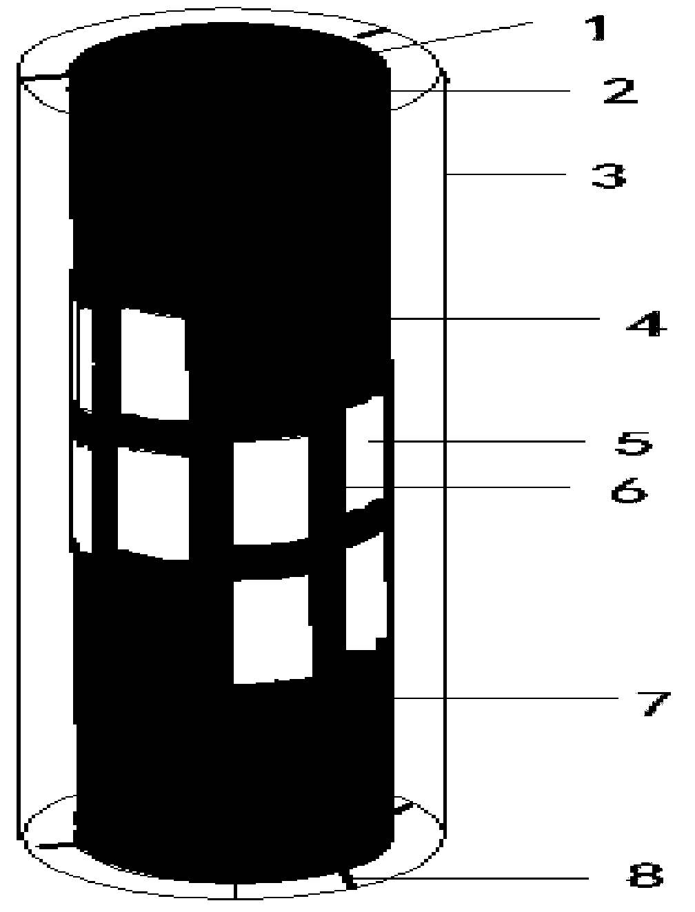
[0017] The invention provides a capacitance tomography sensor with a spiral structure electrode, the sensor includes a main body structure part and a capacitance measurement part. Be described below in conjunction with accompanying drawing.

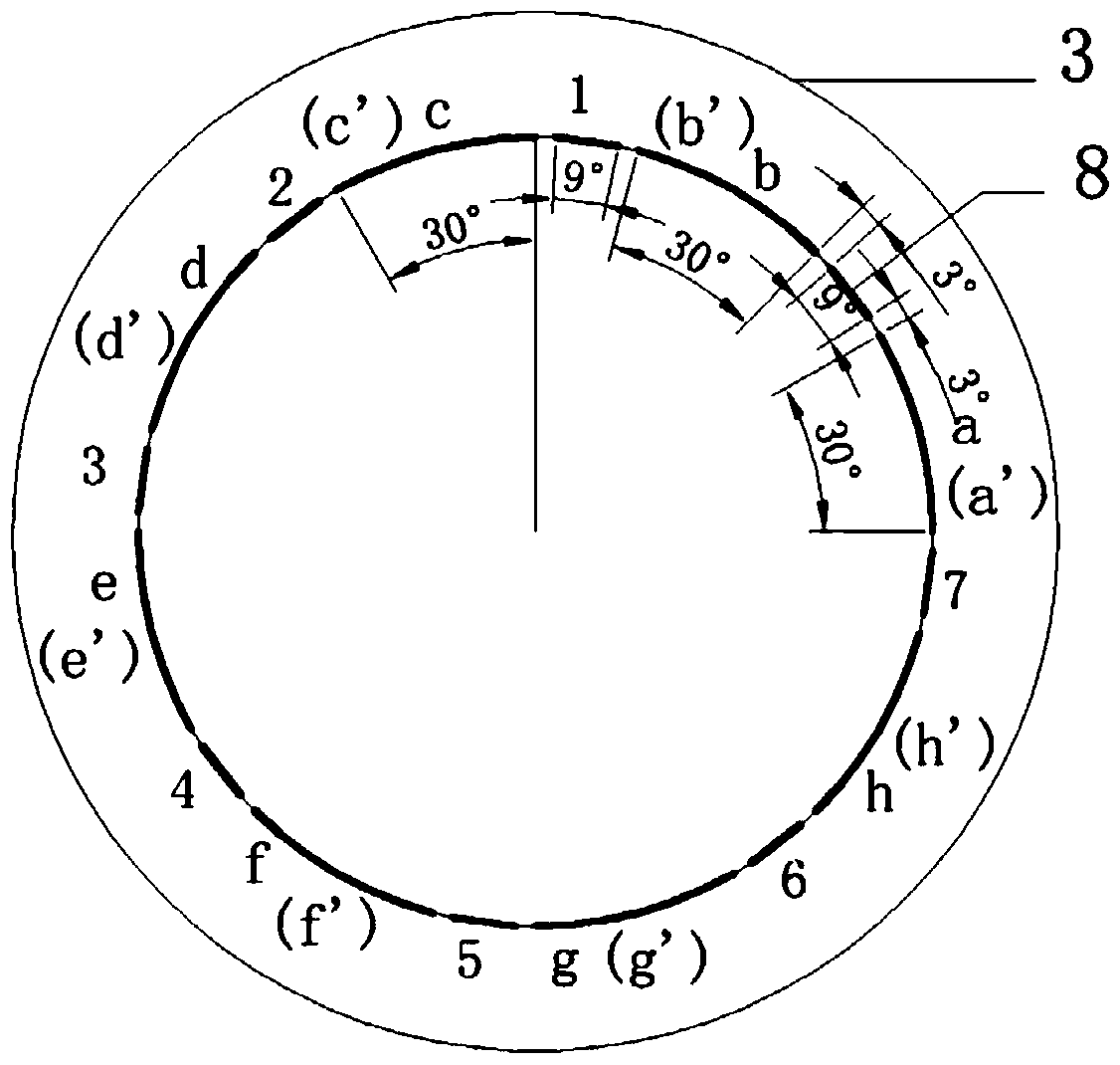
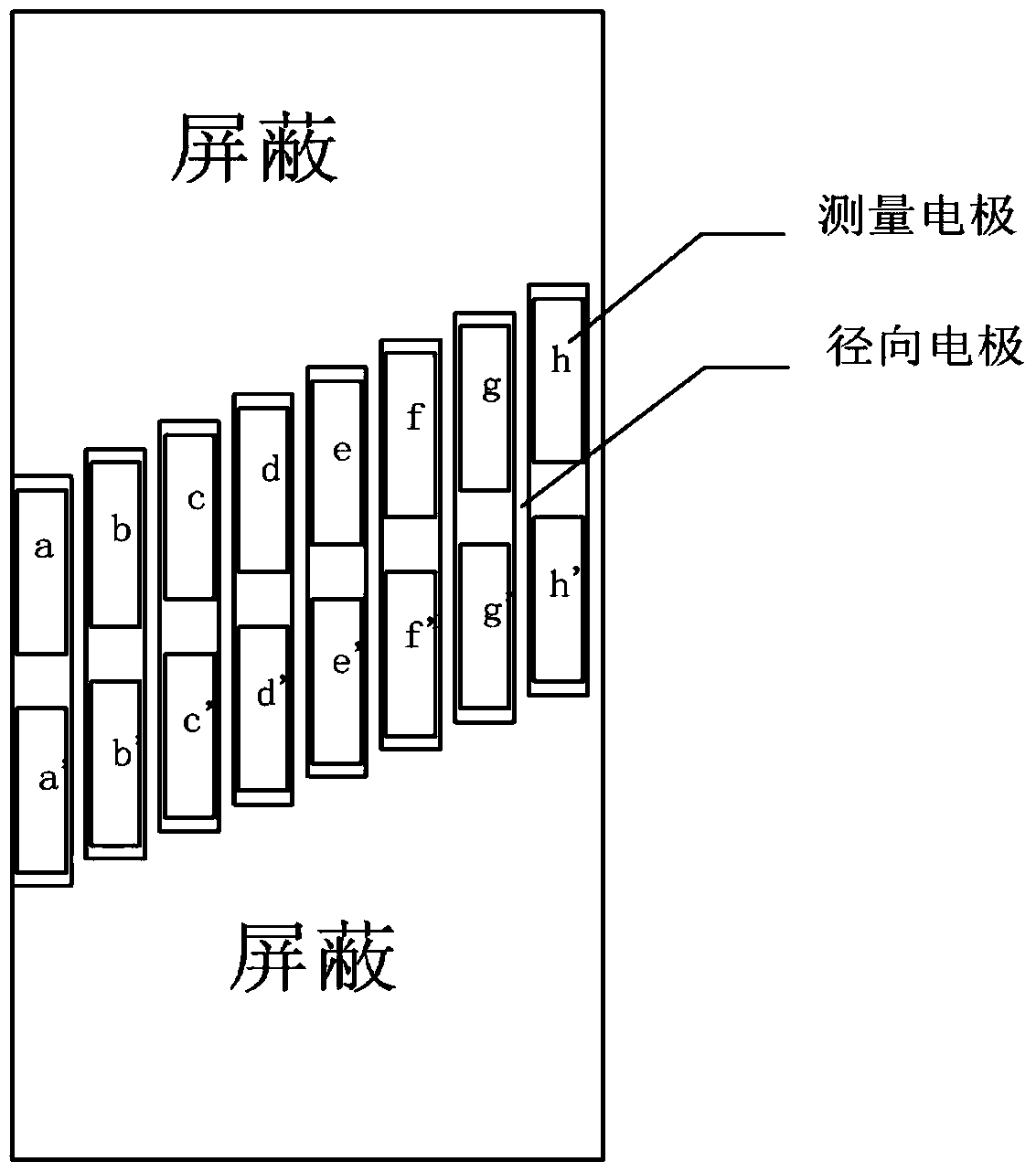
[0018] figure 1 Shown is a schematic diagram of the electrical capacitance tomography sensor structure. The main structure shown in the figure is composed of an insulating tube 1 and a fixed bracket 8. The circular space in the insulating tube is the measured space 2; the capacitance measurement part is to arrange radial electrodes 6 between the detection electrodes 5, and the detection electrodes 5 are in the form of Helically arranged on the outside of the insulating tube 1, divided into two circles, each circle has 8 electrodes, a total of 16 electrodes, rising continuously and evenly (such as image 3 shown). The electrode terminal shield is arranged at the upper and lower ends of the insulating tube 1, and the side close to the me...


PUM


Abstract

The invention discloses an electrical capacitance tomography sensor with helical-structure electrodes, wherein the sensor belongs to the electrical capacitance tomography (ECT) equipment field. The sensor comprises a main body structure part and a capacitance measurement part. The main body structure part is formed by an insulating tube and a fixed support; and the circular space in the insulating tube is measured space. The capacitance measurement part is characterized in that radical electrodes are arranged between detection electrodes; and the radial electrodes are connected with electrode ends in a shielding mode. When the sensor works, capacitance values obtained by measuring the electrodes are transmitted to ECT signal acquisition equipment by signal transmission cables arranged at surfaces of the detection electrodes; after signal processing, detected capacitance signals are converted into electrical signals; the signals are transmitted to a computer terminal; and then the signals are reconstructed to form images based on a reconstruction algorithm of the computer. According to the invention, thermal parameter information including material position distribution, shapes, temperatures, humidity, and flowing speeds, and directions and the like of materials at any place in the measured space at the axial direction can be reconstructed, so that the major breakthrough of the ECT detection technology in terms of three-dimensional imaging is also realized.

Description

technical field [0001] The invention belongs to the scope of an electric capacitance tomography imaging device, in particular to an electric capacitance tomography sensor with a spiral structure electrode. Background technique [0002] Electrical Capacitance Tomography (ECT) is a multiphase flow parameter detection technology developed in the mid-1980s. ECT technology is based on the capacitance sensitive mechanism. When the shape and distribution of the multiphase flow medium in the measured area changes, it will cause the capacitance value between the detection capacitor plates to change, so as to reconstruct the multiphase flow in the measured area through the reconstruction algorithm. distribution image. [0003] The source of the capacitance of the ECT system is the sensor. The traditional ECT sensor is mostly a two-dimensional sensor structure arranged in a single layer, generally an array structure of 8, 12, and 16 electrodes. These electrodes are only arranged aroun...

Claims


Application Information

Patent Timeline
Patent Type & Authority Patents(China)
IPC IPC(8): G01D5/24
CPCG01D5/2405
Inventor 周琬婷姜越刘石刘婧
Owner NORTH CHINA ELECTRIC POWER UNIV (BAODING)
Learn More