
Automatic temperature control methane fermentation device

A biogas fermentation and fermentation tank technology, applied in the field of automatic temperature-controlled biogas fermentation devices, can solve the problems of low production technology, easy to be affected by ambient temperature, and large differences in environmental factors, so as to achieve energy saving, stable biogas output and quality , the effect of simple structure

Active Publication Date: 2016-04-06
JIANGSU POLYTECHNIC COLLEGE OF AGRI & FORESTRY
View PDF5 Cites 3 Cited by
  • Summary
  • Abstract
  • Description
  • Claims
  • Application Information

AI Technical Summary

Problems solved by technology

[0002] As a bioenergy with relatively low production technology and relatively easy promotion, biogas has been strongly recommended by the state and has been widely promoted throughout the country. However, my country has a vast territory and large differences in environmental factors. In some areas, the temperature difference between summer and winter is large. However, the production of biogas, whether it is output or quality, is easily affected by the ambient temperature.

Method used


Image

  • Automatic temperature control methane fermentation device
  • Automatic temperature control methane fermentation device
  • Automatic temperature control methane fermentation device

Examples


Embodiment 1

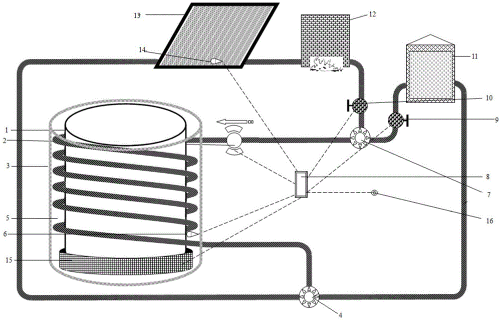
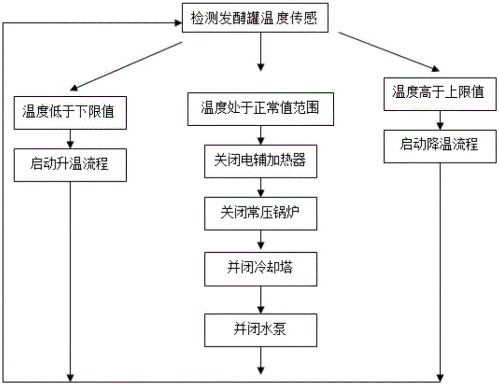
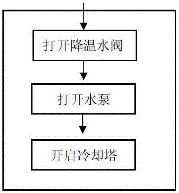
[0024] Such as Figure 1-4 As shown, an automatic temperature control biogas fermentation device includes a fermenter 1, a housing 3, a heat exchange tube 2, a heating system, a cooling system, a first temperature sensor 6, a control template 8 and a biogas pressure probe; the housing 3 is set A cavity structure is formed on the periphery of the fermentation tank 1, and the cavity part is the middle hot water layer 5; the heat exchange tube 2 is spirally wound on the outer wall of the fermentation tank 1 from top to bottom, and both ends of the heat exchange tube 2 are connected with the heating system and the cooling system Connected to form a circuit; the upper and lower heat exchange pipes 2 and the heating system and cooling system are respectively provided with a first water pipe collection hub 7, a second water pipe collection hub 4, and a connection between the fermentation tank 1 and the first water pipe collection hub 7 A water pump is provided on the heat exchange pi...

Embodiment 2

[0028] It is basically the same as Embodiment 1, except that the heating system is an atmospheric boiler 12, one end of the water tank of the atmospheric boiler 12 is connected to the first water pipe collection hub 7, and the other end is connected to the second water pipe collection hub 4; the first temperature There are more than 3 sensors 6, which are evenly arranged on the outer wall, middle and lower part of the fermenter 1.


PUM


Abstract

The invention discloses an automatic temperature control methane fermentation device. The device comprises a fermentation tank, a shell, a heat exchange tube, a heating system, a cooling system, a first temperature sensor, a control template and a methane pressure probe, wherein the shell is arranged on the periphery of the fermentation tank to form a cavity structure, and a middle hot water layer is arranged in the cavity portion; the heat exchange tube is wound around the outer wall of the fermentation tank in a spiral mode, and the two ends of the heat exchange tube are communicated with the heating system and the cooling system to form a circuit; a first water pipe gather junction and a second water pipe gather junction are arranged at the positions where the heat exchange tube is connected with and intersects with the heating system and the cooling system respectively, a water pump, a heating water valve and a cooling water valve are arranged on the heat exchange tube, and the first temperature sensor is arranged on the outer wall of the fermentation tank; the methane pressure probe is arranged in a methane storage bag, and the control template is connected with the first temperature sensor, the water pump, the heating water valve, the cooling water valve and the methane pressure probe. An automatic control device is adopted, and relative stability of the yield and quality of methane is guaranteed.

Description

Technical field [0001] The invention relates to an automatic temperature-controlled biogas fermentation device. Background technique [0002] As a bioenergy with relatively low production technology and easy promotion, biogas is strongly recommended by the country and widely promoted across the country. However, our country has a vast territory and environmental factors vary greatly. In some areas, the temperature difference between summer and winter is large. Biogas production, both in terms of output and quality, is easily affected by ambient temperature. Contents of the invention [0003] Purpose of the invention: In order to overcome the shortcomings of the existing technology, the present invention aims to provide an automatic temperature-controlled biogas fermentation device. [0004] Technical solution: In order to solve the above technical problems, the present invention adopts the following technical solution: [0005] An automatic temperature-controlled biogas ...

Claims


Application Information

Patent Timeline
Patent Type & Authority Applications(China)
IPC IPC(8): C12M1/38C12M1/107C12M1/02
CPCC12M21/04C12M41/18Y02E50/30
Inventor 曹正洪炜高为将
Owner JIANGSU POLYTECHNIC COLLEGE OF AGRI & FORESTRY
Learn More