A bogie forced guiding mechanism

A guiding mechanism and frame technology, which is applied in the design and manufacture of rolling stock bogies, and in the field of rolling stock structure design, can solve problems such as difficult installation of forced guiding mechanisms, increase adhesion utilization, reduce wear, and save manufacturing costs Effect

Inactive Publication Date: 2017-10-27
SOUTHWEST JIAOTONG UNIV
View PDF7 Cites 0 Cited by
  • Summary
  • Abstract
  • Description
  • Claims
  • Application Information

AI Technical Summary

Problems solved by technology

When the steerable bogie passes through the curve, the relative angular displacement between the car body and the bogie is used to force the wheelset to be in the radial position. At present, the relatively mature design schemes include the DEVINE-SCALE bogie in the United States. The levers they use connect the front and rear The length of the wheel shaft and the lever is related to the distance between the front and rear wheel shafts. If there is an intermediate wheel shaft and motor, the forced guide mechanism will be difficult to install

Method used


Image

  • A bogie forced guiding mechanism
  • A bogie forced guiding mechanism
  • A bogie forced guiding mechanism

Examples


Embodiment Construction

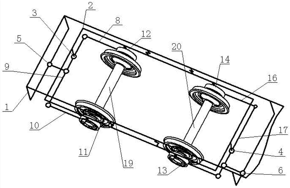
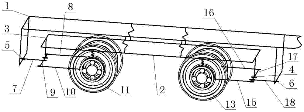
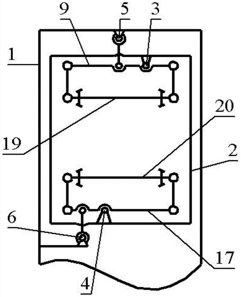
[0021] A bogie force guide mechanism, including a frame 2 supporting the car body 1, a left front axle box 11 and a right front axle box 12 are correspondingly provided at the left and right ends of the front axle 19 wheel sets, and a left front axle box 12 is correspondingly provided at the left and right ends of the front beam 9. Tie rod 10, right front tie rod 8, one end of left front tie rod 10 is hinged to left front axle box 11, the other end is hinged to left end of front crossbeam 9, one end of right front tie rod 8 is hinged to right front axlebox 12, the other end is hinged to front crossbeam 9 right end; rear axle 20 The left and right ends of the wheel pair are correspondingly provided with a left rear axle box 13 and a right rear axle box 14, and the left and right ends of the rear beam 17 are correspondingly provided with a left rear tie rod 15 and a right rear tie rod 16, and one end of the left rear tie rod 15 is connected to the left rear axle. The box 13 is hi...


PUM


Abstract

The invention discloses a bogie forced guide mechanism, which belongs to the technical field of locomotive and vehicle structure design, and can effectively solve the problem that the vehicle is limited by the axle distance when using the forced guide frame. Including the car body and frame, the front guide rod connecting the front cross beam and the car body, the rear guide rod connecting the rear cross beam and the car body; one end of the left front tie rod is hinged on the left front axle box, the other end is hinged on the left end of the front cross beam, and one end of the right front tie rod is hinged On the right front axle box, the other end is hinged on the right end of the front crossbeam. One end of the left rear tie rod is hinged on the left rear axlebox, and the other end is hinged on the left end of the rear crossbeam. Right end of the rear cross member. The front cross beam is hinged at the right position of the frame center, and the rear cross beam is hinged at the left position of the frame center. One end of the front guide rod is hinged at the front end of the vehicle body, and the other end is hinged at the front beam; one end of the rear guide rod is hinged at the rear end of the vehicle body, and the other end is hinged at the rear beam. Mainly used in the manufacture of rolling stock.

Description

technical field [0001] The invention belongs to the technical field of locomotive and vehicle structure design, in particular to the technical field of design and manufacture of locomotive and vehicle bogies. Background technique [0002] During the operation of railway locomotives in the curve section, the wheel-rail creep force realizes the radial position of the wheel set on the curve through the radial adjustment mechanism, which can effectively reduce the friction and wear of the wheel-rail, and the self-guiding bogie relies entirely on creep Force steering has certain limitations, and can only partially improve the curve passing performance, while the curve passing performance of the forced steerable bogie is better than that of the self-steering bogie. When the steerable bogie passes through the curve, the relative angular displacement between the car body and the bogie is used to force the wheelset to be in the radial position. At present, the relatively mature desig...

Claims


Application Information

Patent Timeline
Patent Type & Authority Patents(China)
IPC IPC(8): B61F5/38B61F5/48B61F5/22
CPCB61F5/22B61F5/38B61F5/48
Inventor 史炎马卫华
Owner SOUTHWEST JIAOTONG UNIV
Why Eureka
Try Eureka