
Clamping apparatus of variable-pitch flexible robot

A fixture and flexible technology, applied in the field of tool fixtures, can solve the problems of low work efficiency, time-consuming and labor-intensive, limited suction range of ice cream, etc., and achieve the effect of simple structure and convenient use

Active Publication Date: 2016-04-06
苏州澳昆智能机器人技术有限公司
View PDF9 Cites 8 Cited by
  • Summary
  • Abstract
  • Description
  • Claims
  • Application Information

AI Technical Summary

Problems solved by technology

At present, most ice cream manufacturers still use the method of manual packing, that is, packing workers sit on both sides of the finished ice cream conveyor line. When the finished ice cream is running along the conveyor line, the packing workers pick up the corresponding quantity according to the size of the packing box. Ice cream is put into packing boxes in layers. This method is time-consuming and labor-intensive, requiring a large amount of labor but low work efficiency. At present, some manufacturers use various tools and fixtures to realize the grabbing and packing of ice cream. For example, the application number is 201220224454.3. The fixture has an integral negative pressure chamber and the negative pressure in the negative pressure chamber is not only balanced but not easy to drop parts, it is suitable for grabbing and packing ice cream of different specifications and shapes; but because the entire fixture is made of hard materials Made, so that the suction range is limited and the amount of ice cream that is sucked at a time is small and the ice cream is easy to be damaged. At the same time, it cannot be adjusted according to the real-time position of the ice cream, and it cannot be applied to the current ice cream packing requirements with a wide variety and different spacing.

Method used


Image

  • Clamping apparatus of variable-pitch flexible robot
  • Clamping apparatus of variable-pitch flexible robot

Examples


Embodiment 1

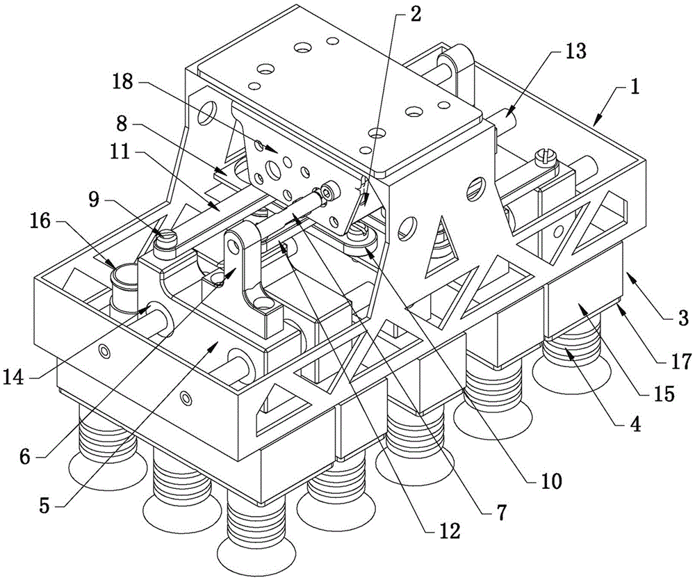
[0020] Such as figure 1 As shown, five suction cups 3 are arranged in the jig frame 1 of the pitch-variable flexible robot jig of the present invention, and three suction cup soft joints 4 are arranged on the cavity cover plate 17 of each suction cup 3. 1 is provided with two guide rods 13, and five suction cups 3 are all installed on the guide rods 13 through the connecting block 5, wherein the middle suction cup 3 is fixedly arranged under the frame positioning plate 8 and does not move along the fixture frame 1. The connecting block 5 located at both ends of the fixture frame 1 in the length direction is fixed with a cylinder push block 6, and the cylinder push block 6 is connected with the piston rod of the corresponding cylinder 2 through the corresponding cylinder connecting rod 7, and has a cylinder The connecting block 5 of the push block 6 is connected with the corresponding main connecting rod 10 arranged on the frame positioning plate 8 through the active support co...


PUM


Abstract

The invention discloses a clamping apparatus of a variable-pitch flexible robot. The clamping apparatus comprises a clamping apparatus framework (1). The bottom of a top plate of the clamping apparatus framework (1) is provided with two cylinders (2) opposite in driving direction. At least two suckers (3) are arranged in the clamping apparatus framework (1). The bottoms of the suckers (3) are provided with sucker flexible joints (4). Connecting blocks (5) are fixedly installed on the suckers (3). Meanwhile, cylinder push blocks (6) are fixedly arranged on the connecting blocks (5) on the sides of the two ends of the clamping apparatus framework (1) in the length direction of the clamping apparatus framework (1) and are connected with piston rods of the cylinders (2) through corresponding cylinder connecting rods (7). When the piston rods of the two cylinders (2) stretch out, the corresponding suckers (3) are far away from each other, and otherwise, the corresponding suckers (3) get close to each other. The clamping apparatus can adjust the distance between the suckers in real time, the binning requirement of ice cream of different kinds and at different intervals is met, and the application range is wide.

Description

technical field [0001] The invention relates to a tool fixture, in particular to a pitch-variable flexible robot tool fixture for a robot, which runs stably and can synchronously extend and contract the suction cups to adjust the distance between the suction cups. Background technique [0002] After the existing ice cream is prepared, it needs to be placed in a packing box for storage and transportation. At present, most ice cream manufacturers still use the method of manual packing, that is, packing workers sit on both sides of the finished ice cream conveyor line. When the finished ice cream is running along the conveyor line, the packing workers pick up the corresponding quantity according to the size of the packing box. Ice cream is put into packing boxes in layers. This method is time-consuming and labor-intensive, requiring a large amount of labor but low work efficiency. At present, some manufacturers use various tools and fixtures to realize the grabbing and packing ...

Claims


Application Information

Patent Timeline
IPC IPC(8): B25J9/00B25J9/14B25J15/06
CPCB25J9/0009B25J9/14B25J15/0616
Inventor 李政德刘霞
Owner 苏州澳昆智能机器人技术有限公司
Learn More