


Quick Research
Generate reliable direction feasibility study reports for your R&D in just a few steps.

Technical Q&A
Discover and master advanced knowledge NOW. Basics, ideas, possibilities, all at once.

Find Solutions
As an expert in R&D theories, this can generate solutions to your technical problems instantly.

Evaluate Feasibility
Analyze your overall solution with one click, know your potential R&D risks in advance.

Monitor Landscape
Get weekly tech updates, stay abreast of the latest tech innovations and key insights.
Method for monitoring a brake and brake which is monitored by the method
A technology of brakes and brake discs, applied in the direction of brakes, brake types, brake components, etc., can solve the problems that the brakes cannot always provide reliable results, and achieve the effect of avoiding fault reports
- Summary
- Abstract
- Description
- Claims
- Application Information
AI Technical Summary
Problems solved by technology
Method used
Image


Examples
Embodiment Construction
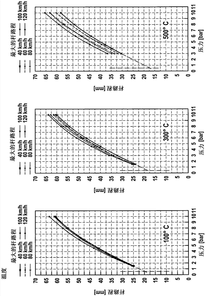
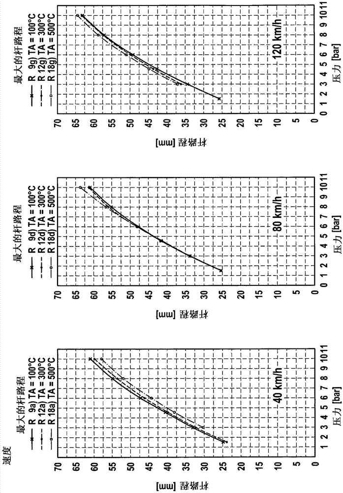
[0044] according to figure 1 and 2 The graphs of , respectively, show the maximum lever travel for disc brakes at different temperatures or at different speeds as a function of brake pressure. It shows that the individual maximum lever distances, brake pressure, temperature and speed are interrelated or dependent on each other. Rod path is a measure for clearance.
[0045] as can especially be obtained from figure 1 At a brake pressure of 10bar and a speed of 40km / h, the maximum lever travel
[0046] 61mm at a temperature of 100°C,
[0047] 60mm at a temperature of 300°C, and
[0048] It is 57.5mm at a temperature of 500°C.
[0049] according to figure 2 , when the brake pressure is 10bar and the temperature is 500℃, the maximum rod travel
[0050] 58mm at a speed of 40km / h,
[0051] 64mm at a speed of 80km / h, and
[0052] It is 64.5mm at a speed of 120km / h.
[0053] The temperatures are each the temperature of one of the participating brake linings. Since the bra...
PUM
 Abstract
Description
Claims
Application Information
 - R&D Engineer
- R&D Manager
- IP Professional
- Industry Leading Data Capabilities
- Powerful AI technology
- Patent DNA Extraction
Browse by: Latest US Patents, China's latest patents, Technical Efficacy Thesaurus, Application Domain, Technology Topic, Popular Technical Reports.
© 2024 PatSnap. All rights reserved.Legal|Privacy policy|Modern Slavery Act Transparency Statement|Sitemap|About US| Contact US: help@patsnap.com