Eureka AIR delivers breakthrough ideas for toughest innovation challenges, trusted by R&D personnel around the world.

Cabinet

A cabinet and rear cabinet door technology, which is applied in the direction of cabinet/cabinet/drawer parts, electrical equipment shell/cabinet/drawer, electrical components, etc. Solve problems such as small tank capacity, achieve good support, improve safety, and expand capacity

Inactive Publication Date: 2016-03-30
XINJINWEI NETWORK TECH
View PDF0 Cites 3 Cited by
  • Summary
  • Abstract
  • Description
  • Claims
  • Application Information

AI Technical Summary

Problems solved by technology

A structural design of the cabinet is generally only suitable for the situation where the power socket is located in one position, and is limited by the placement or installation controls, so the adaptability is poor
Generally speaking, wire slots are set in the cabinet to bundle the various lead wires during use, but conventional cabinets often encounter problems such as too small wire slot capacity. In this case, the redundant wire harness must be fixed Outside the wire slot, tie it tightly with a thin rope, steel wire or buckle belt. There are two main defects in this way: the first is that there are potential safety hazards, and the second is that the wiring harness is confusing and difficult to identify, which is not conducive to the connection between the wiring harness and electrical equipment.
The wiring harness inside the cabinet is too messy, the wiring hole is single, and the safety is poor

Method used


Image

  • Cabinet
  • Cabinet

Examples


Embodiment Construction

[0013] Specific embodiments of the invention will be described in detail below in conjunction with the accompanying drawings.

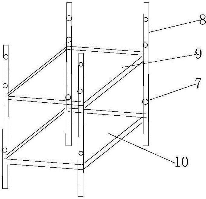
[0014] Such as Figures 1 to 2 As shown, it includes a front cabinet door 1, a rear cabinet door, a left side panel, a right side panel 4, an upper top panel 2, a lower bottom panel 3, an upper beam 9, a lower beam 10, and four column-shaped trunkings 8. The cabinet is provided with There is a front cabinet door 1, the front cabinet door 1 is provided with a handle 5, the cabinet is provided with a rear cabinet door with a number of cooling holes, and the upper top board 2 and the lower bottom board 3 are respectively installed on the two side boards and the rear cabinet On the door, the upper top plate is provided with a threading hole 7 near the rear cabinet door, and the lower bottom plate 3 is provided with an opening near the front section, and the wiring harness can pass in and out through the wiring hole or opening. The upper top plate 2 and th...


PUM


Abstract

The present invention provides a cabinet. The cabinet comprises a front cabinet door, a back cabinet door, a left side plate, a right plate, an upper top plate, a lower bottom plate, an upper beam, a lower beam and four upright wire ducts. The front cabinet door is provided with a handle; a punched hole is arranged at the position of the upper top plate close to the back cabinet door; an opening is arranged at the position of the lower bottom plate close to the front cabinet door; a wiring harness is able to pass through the punched hole or the opening; the front cabinet door is fixed on the left side plate through screws; the upper end and the lower end of each wire duct are respectively fixed at the upper top plate and the lower bottom plate through nuts; the wiring on the ducts is extended between the support pieces on the upper beam and the lower beam so that scrambled wiring harness is avoided in the cabinet, therefore the safety of the cabinet is greatly improved, and the adaptability is good.

Description

technical field [0001] The invention belongs to the field of communication equipment, and in particular relates to a cabinet. Background technique [0002] In today's society, with the rapid development of communication technology, less parts, easy maintenance and installation have become an important development direction of communication equipment. The cabinet is a mechanical device belonging to the communication field, and is usually used to store network devices such as servers, hubs, and disk showcases. A structural design of the cabinet is generally only applicable to the situation where the power socket is located at one position, and is limited by placement or installation controls, and has poor adaptability. Generally speaking, wire slots are set in the cabinet to bundle the various lead wires during use, but conventional cabinets often encounter problems such as too small wire slot capacity. In this case, the redundant wire harness must be fixed Outside the wire ...

Claims


Application Information

Patent Timeline
Patent Type & Authority Applications(China)
IPC IPC(8): H05K5/00H05K5/02
Inventor 郝铁乱张永花
Owner XINJINWEI NETWORK TECH
Why Eureka
Eureka Blog
Learn More