
An envelope deposit gate mechanism

A gate and deposit technology, which is applied in the field of financial equipment, can solve the problems of being unable to apply in places with limited space, damaging the motor and mechanical structure, and large installation space of the gate mechanism, so as to achieve compact structure, uniform force, improved stability and reliability effect

Active Publication Date: 2017-11-17
HEBEI HUIJIN ELECTROMECHANICAL
View PDF8 Cites 0 Cited by
  • Summary
  • Abstract
  • Description
  • Claims
  • Application Information

AI Technical Summary

Problems solved by technology

[0002] The gate mechanisms of some self-service financial equipment currently on the market have two modes of action: horizontal placement (or tilting at a certain angle) and rotation around the axis, and the opening and closing ranges of these two modes are relatively large. The installation space caused by opening and closing is also large, and it cannot be applied to places with limited space, and the opening and closing range of the gate is relatively large, and most of the motors cannot rotate within an arbitrary angle range. If the sensors for the start and end positions fail, there is a risk of damage to the motor and mechanical structure
In addition, the design of the gate is limited by space, and the power of the motor can only be placed on one side of the gate, so that the force on the gate is not very uniform, and the stability and life of the mechanism will also be affected to a certain extent.

Method used


Image

  • An envelope deposit gate mechanism
  • An envelope deposit gate mechanism
  • An envelope deposit gate mechanism

Examples


Embodiment Construction

[0024] The following will clearly and completely describe the technical solutions in the embodiments of the present invention with reference to the accompanying drawings in the embodiments of the present invention. Obviously, the described embodiments are only some, not all, embodiments of the present invention. Based on the embodiments of the present invention, all other embodiments obtained by persons of ordinary skill in the art without making creative efforts belong to the protection scope of the present invention.

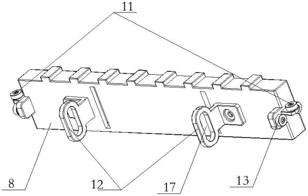
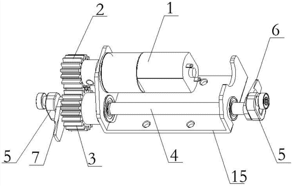
[0025] see Figure 1~6 , in an embodiment of the present invention, an envelope deposit gate mechanism includes a driven gear shaft 4, a crank 5, a gate 8 and a gate frame 9, symmetrical horizontal bearings 11 are installed at both ends of the gate 8, and the two ends of the gate 8 are also A symmetrical first vertical bearing 13 is installed; a symmetrical L-shaped connecting rod 12 is also fixedly installed on the gate 8, and the L-shaped connecting rod 12 i...


PUM


Abstract

The invention discloses an envelope deposit gate mechanism. The envelope deposit gate mechanism comprises a driven gear shaft, cranks, a gate and a gate frame; two ends of the gate are respectively provided with symmetrical horizontal bearings and symmetrical vertical bearings; the gate is also provided with symmetrical L-shaped connecting rods; horizontal sliding slots of two ends of the gate frame are matched with the vertical bearings; the gate is arranged on the gate frame in a sliding manner through the matching between the vertical bearings and the horizontal sliding slots; the driven gear shaft is installed on the support of the gate frame; the cranks are installed at two ends of the driven gear shaft respectively; the cranks are provided with second vertical bearings vertical; and vertical sliding slots are matched with the second vertical bearings; two ends of the driven gear shaft are respectively provided with a sensor catch; and the gate frame is provided with symmetrical sensors. The gate mechanism of the invention has the advantages of compact structure, small opening and closing range and small occupied space. According to the gate mechanism, the envelope space of the movement of the gate can be reduced, and the gate can be uniformly stressed, and therefore, the stability and the reliability of the gate can be improved.

Description

technical field [0001] The invention relates to the field of financial equipment, in particular to an envelope deposit gate mechanism used by financial institutions. Background technique [0002] The gate mechanisms of some self-service financial equipment currently on the market have two modes of action: horizontal placement (or tilting at a certain angle) and rotation around the axis, and the opening and closing ranges of these two modes are relatively large. The installation space caused by opening and closing is also large, and it cannot be applied to places with limited space, and the opening and closing range of the gate is relatively large, and most of the motors cannot rotate within an arbitrary angle range. If the sensors for the start and end positions fail, there is a risk of damage to the motor and the mechanics. In addition, the design of the gate is limited by space, and the power of the motor can only be placed on one side of the gate, so that the force on th...

Claims


Application Information

Patent Timeline
Patent Type & Authority Patents(China)
IPC IPC(8): G07D11/00
CPCG07D11/10G07D11/14
Inventor 李毅
Owner HEBEI HUIJIN ELECTROMECHANICAL
Learn More