
Printing ink motion controllable electrowetting display and preparation method thereof

An electrowetting display and motion technology, applied in the direction of instruments, optical components, optics, etc., can solve problems such as uneven electric field, lower pixel turn-on voltage, and inability to effectively control the position of ink rupture

Active Publication Date: 2016-03-30
SHENZHEN GUOHUA OPTOELECTRONICS +2
View PDF6 Cites 6 Cited by
  • Summary
  • Abstract
  • Description
  • Claims
  • Application Information

AI Technical Summary

Problems solved by technology

A large number of experiments and theoretical simulation results show that the selection of the ink rupture point and the position of the thinnest ink thickness occur preferentially, and the threshold voltage required for ink rupture depends on the thickness of the thinnest part of the ink; obviously the role of notch is to control the shrinkage end point of the ink position, unable to effectively control the cracking position of the ink and reduce the turn-on voltage of the pixel
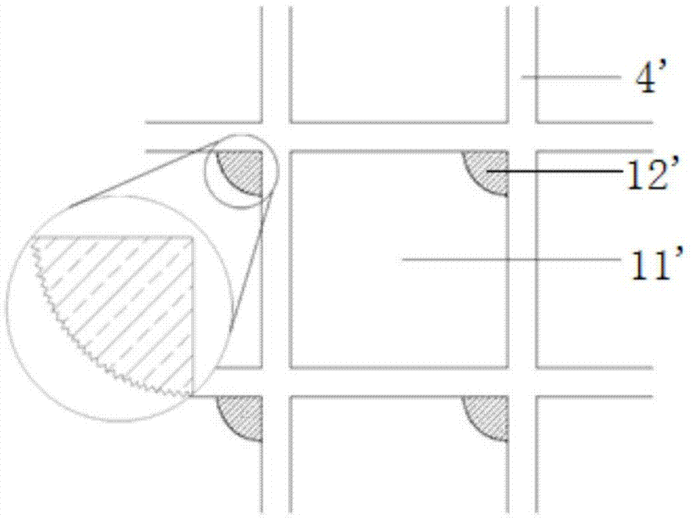
More importantly, in the process of etching the conductive backplane (such as the commonly used ITO conductive glass) to make the notch, it is easy to appear such as figure 1 The irregular jagged edge shown in the enlarged picture in the figure, when powered on, the electric field will be uneven due to the charge distribution layout on the jagged edge, and the charge will tend to gather at the irregular conductive tip during the electrical measurement. The formed local high charge density is very easy to cause the breakdown of the insulating layer, causing the display to be damaged

Method used


Image

  • Printing ink motion controllable electrowetting display and preparation method thereof
  • Printing ink motion controllable electrowetting display and preparation method thereof
  • Printing ink motion controllable electrowetting display and preparation method thereof

Examples


Embodiment Construction

[0024] The idea, specific structure and technical effects of the present invention will be clearly and completely described below in conjunction with the embodiments and accompanying drawings, so as to fully understand the purpose, features and effects of the present invention. Apparently, the described embodiments are only some of the embodiments of the present invention, rather than all of them. Based on the embodiments of the present invention, other embodiments obtained by those skilled in the art without creative efforts belong to The protection scope of the present invention. In addition, all the connection / connection relationships involved in the patent do not simply refer to the direct connection of components, but mean that a better connection structure can be formed by adding or reducing connection accessories according to specific implementation conditions. The various technical features in the invention can be combined interactively on the premise of not conflictin...


PUM


Abstract

The invention discloses a printing ink motion controllable electrowetting display and a preparation method thereof. The printing ink motion controllable electrowetting display comprises a conducting layer, an insulating layer and a pixel wall, wherein the insulating layer is arranged on the upper surface of the conducting layer; the pixel wall is arranged on the upper surface of the insulating layer; the insulating layer is a double-layer insulating layer; the double-layer insulating layer includes a hydrophilic insulating layer and a hydrophobic insulating layer; the hydrophilic insulating layer fully covers the upper surface of the conducting layer; the hydrophobic insulating layer covers the upper surface of the hydrophilic insulating layer; in a pixel grid, the hydrophobic insulating layer exposes part of the upper surface of the hydrophilic insulating layer; the thickness of the printing ink decreases progressively from one side of the hydrophobic insulating layer to one side of the hydrophilic insulating layer; and after the voltage is applied, the printing ink is cracked at the most thin part, and contracts from one side of the hydrophilic insulating layer to one side of the hydrophobic insulating layer so that effective control of the cracked position of the printing ink and the printing ink motion contraction direction when an electrowetting display pixel unit is powered up.

Description

technical field [0001] The invention relates to the technical field of electrowetting display devices, in particular to an electrowetting display with controllable ink movement and a preparation method thereof. Background technique [0002] refer to Figure 1-2 , a traditional electrowetting display includes a first substrate and a second substrate, the first substrate includes an upper substrate 1', an upper conductive layer 2' and an encapsulation frame 3', the second substrate includes a lower substrate 6', a lower conductive layer 9 ', insulating layer 8', hydrophobic layer 5', pixel wall 4', ink 10' and electrolyte solution 7' ​​are filled between the first substrate and the second substrate, wherein the ink 10' is filled in by the pixel wall 4' within the enclosed pixel grid 11'. The switching of the electrowetting display pixel unit starts with the rupture of the ink, followed by the formation of non-polar liquid (ink 10') / polar liquid (electrolyte solution 7') / s...

Claims


Application Information

Patent Timeline
Patent Type & Authority Applications(China)
IPC IPC(8): G02B26/00
CPCG02B26/005
Inventor 唐彪蒋洪伟周敏赵青罗伯特·安德鲁·海耶斯周国富
Owner SHENZHEN GUOHUA OPTOELECTRONICS
Learn More