A few-mode fiber

A technology of few-mode fiber and fiber, applied in clad fiber, multi-core fiber, micro-structure fiber, etc., can solve the problems of large bending loss, difficult work, G.652 fiber can not meet the requirements, etc., and achieve low bending loss transmission , maintain low-loss transmission, and achieve the effect of single-mode operation

Active Publication Date: 2018-08-28
INFORMATION & COMMNUNICATION BRANCH STATE GRID JIANGXI ELECTRIC POWER CO +2
View PDF4 Cites 0 Cited by
  • Summary
  • Abstract
  • Description
  • Claims
  • Application Information

AI Technical Summary

Problems solved by technology

However, the conventional G.652 optical fiber can work with a minimum bending radius of 30mm, but a smaller bending radius is required in metropolitan area networks, local area networks, fiber-to-the-home, and short-distance communications, and G.652 optical fibers can no longer meet the requirements
The G.657 optical fiber proposed internationally solves the problems existing in the G.652 optical fiber, and can work at a bending radius of 7.5mm or even 5mm, but the bending loss of the G.657 optical fiber is relatively large when it works at a small bending radius , it is difficult to achieve long-term stable work under small bending radius

Method used


Image

  • A few-mode fiber
  • A few-mode fiber
  • A few-mode fiber

Examples


Embodiment 1

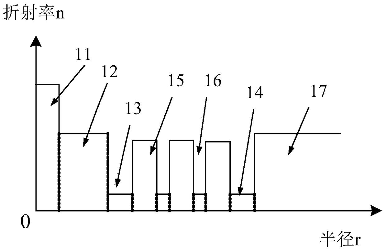
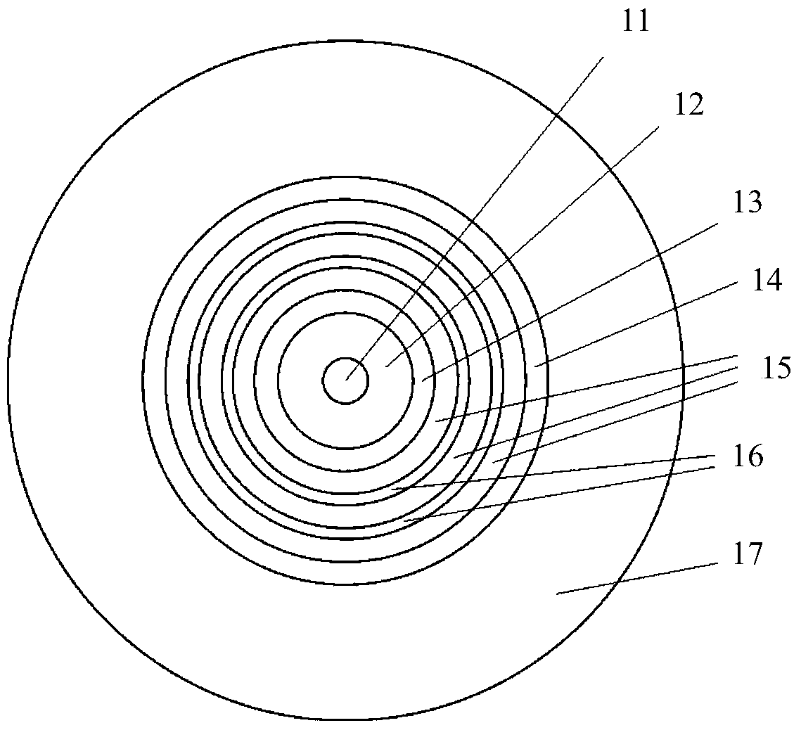
[0052] The radius a of the inner core 11 1 =4.1μm, the radial width a of the outer core 12 2 = 6 μm. The radial width of the adjacent low refractive index layer 13 is 3 μm, the radial width of the adjacent low refractive index layer 14 is 3 μm, the radial width of the high refractive index filter layer 15 is 3 μm, and the radial width of the low refractive index filter layer 16 is 2 μm. The high-refractive index filter layer 15 and the low-refractive index filter layer 16 are three layers and two layers respectively, and the optical fiber structure is shown in FIG. 2 . Inner core 11, outer core 12, core-adjacent low-refractive index layer 13, adjacent-wrap low-refractive-index layer 14, high-refractive-index filter mode layer 15, low-refraction-index filter mode layer 16 and outer cladding layer 17. 1 ,n 2 ,n 3 ,n 4 ,n 5 ,n 6 ,n 7 Satisfied between: n 1 -n 2 =0.005, n 2 -n 3 =0.004, n 2 -n 5 =0.002,n 3 =n 4 =n 6 , n 2 =n 7 .

[0053] When the optical wavel...

Embodiment 2

[0055] The radius a of the inner core 11 1 =4μm, the radial width a of the outer core 12 2 = 6 μm. The radial width of the adjacent low refractive index layer 13 is 3 μm, the radial width of the adjacent low refractive index layer 14 is 3 μm, the radial width of the high refractive index filter layer 15 is 3 μm, and the radial width of the low refractive index filter layer 16 is 2 μm. The high refractive index filter layer 15 and the low refractive index filter layer 16 are two layers and one layer respectively. Inner core 11, outer core 12, core-adjacent low-refractive index layer 13, adjacent-wrap low-refractive-index layer 14, high-refractive-index filter mode layer 15, low-refraction-index filter mode layer 16 and outer cladding layer 17. 1 ,n 2 ,n 3 ,n 4 ,n 5 ,n 6 ,n 7 Satisfied between: n 1 -n 2 =0.005, n 2 -n 3 =0.007, n 2 -n 5 =-0.001, n 3 =n 4 =n 6 , n 2 =n 7 .

[0056] When the optical wavelength is 1550nm, when the bending radius of the optical ...


PUM

PropertyMeasurementUnit
radiusaaaaaaaaaa
radiusaaaaaaaaaa
widthaaaaaaaaaa

Abstract

The invention provides a few-mode optical fiber, which comprises: a core and a cladding; the core comprises: an inner core and an outer core surrounding the inner core; the cladding comprises: surrounding the A core-adjacent low-refractive index layer of the outer core; a microstructure defect region surrounding the adjacent-core low-refractive index layer; the microstructure defect region is composed of a high-refractive-index filter mode layer and a low-refractive-index filter mode layer arranged at intervals ; an adjacent cladding low-refractive index layer surrounding the microstructure defect region; an outer cladding enclosing the adjacent cladding low-refractive index layer. Wherein, the optical fiber is a non-single-mode optical fiber in a straight waveguide state. After proper bending, the high-order mode of the optical fiber is strongly coupled with the defect mode in the microstructure defect region, thereby realizing the filtering of the high-order mode of the optical fiber. The purpose is to realize single-mode transmission.

Description

technical field [0001] The invention relates to the field of optical fiber communication, and more specifically relates to a few-mode optical fiber capable of maintaining low-loss transmission under a small bending radius and capable of realizing single-mode operation. Background technique [0002] With the scientific and technological optical fiber communication technology being widely used in people's daily life and work, it has brought great convenience to people's daily life and work, and has become an indispensable technology in people's daily life and work. [0003] Conventional single-mode optical fiber has a certain ability to resist bending, but in current life, technologies such as metropolitan area network, local area network, fiber-to-the-home, and short-distance communication have been widely used in people's daily life and work. In order to facilitate laying or In order to reduce the space occupied by the optical fiber, the optical fiber needs to work under a s...

Claims


Application Information

Patent Timeline
Patent Type & Authority Patents(China)
IPC IPC(8): G02B6/02G02B6/036
CPCG02B6/02042G02B6/02052G02B6/02295G02B6/03627
Inventor 王华陈明阳殷平蔡志民韦锦田晖李路明杨济海祝远锋
Owner INFORMATION & COMMNUNICATION BRANCH STATE GRID JIANGXI ELECTRIC POWER CO
Why Eureka
Try Eureka