
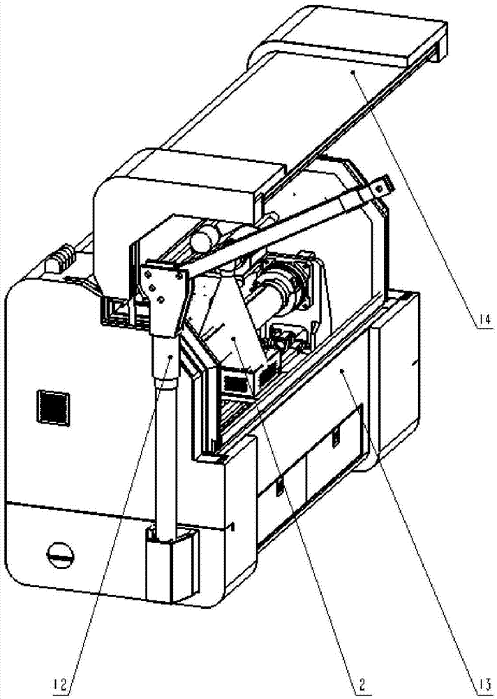
Full-field rod-shaped sample CT scanning device

A CT scanning, full field of view technology, used in measuring devices, instruments, scientific instruments, etc., can solve the problems of large capital investment, large equipment volume, long equipment, etc., and achieve reduced equipment volume, high scanning efficiency, and small rotation radius. Effect

Inactive Publication Date: 2016-03-30
天津三英精密仪器股份有限公司
View PDF7 Cites 3 Cited by
  • Summary
  • Abstract
  • Description
  • Claims
  • Application Information

AI Technical Summary

Problems solved by technology

[0003] CT technology plays an important role in the analysis of the internal results of the core. At present, there are three main types of CT equipment for three-dimensional structure analysis of the internal results of the core, and these three CT equipments have their own disadvantages when used: (1) Using the existing medical CT scans the core, but the equipment is bulky and inconvenient for long-distance transportation, and additional lead room is required, which requires a large capital investment; (2) The core scanner in the form of core translation and rotation is affected by the length of the core, and the equipment is relatively large. Long, inconvenient transportation, difficult to guarantee manufacturing accuracy; (3) core scanning instrument in the form of vertically placed rock core, the ray source rotates and translates up and down, the rotating body of the scanning instrument in this form has a large rotational inertia, and cannot To achieve continuous scanning, the efficiency of the equipment is not high; if a slip ring is used, continuous scanning can be achieved, but it will increase the cost of equipment procurement and maintenance

Method used


Image

  • Full-field rod-shaped sample CT scanning device
  • Full-field rod-shaped sample CT scanning device

Examples


Embodiment Construction

[0026] It should be noted that, in the case of no conflict, the embodiments of the present invention and the features in the embodiments can be combined with each other.

[0027] In describing the present invention, it should be understood that the terms "center", "longitudinal", "transverse", "upper", "lower", "front", "rear", "left", "right", " The orientations or positional relationships indicated by "vertical", "horizontal", "top", "bottom", "inner" and "outer" are based on the orientations or positional relationships shown in the drawings, and are only for the convenience of describing the present invention and Simplified descriptions, rather than indicating or implying that the device or element referred to must have a particular orientation, be constructed and operate in a particular orientation, and thus should not be construed as limiting the invention. In addition, the terms "first", "second", etc. are used for descriptive purposes only, and should not be understood ...


PUM


Abstract

The invention provides a full-field rod-shaped sample CT scanning device. The full-field rod-shaped sample CT scanning device comprises a supporting device and a scanning device; the supporting device comprises a platform, a first supporting frame, and a second supporting frame; the first supporting frame and the second supporting frame are arranged on the two ends of the platform, and are used for supporting a sample to be measured; the scanning device comprises an X ray source and a detector; and the detector is arranged at a position opposite to the position of the X ray source. Flat laying rotating of the sample to be measured, and ray source detector parallel translation are adopted, so that equipment size is reduced, rotating semidiameter of the sample to be measured is reduced compared with that when the ray source and the detector are rotated, inertia is low, and precision is high.

Description

technical field [0001] The invention belongs to the field of detection instruments, in particular to CT scanning equipment for rod-shaped samples with a full field of view. Background technique [0002] CT scanning technology (Computed Tomography), that is, computer tomography, was first used in the field of medical imaging, and was later introduced into the field of industrial non-destructive testing. It has also been well applied in other fields. In these fields, it is often necessary to perform full imaging on strip-shaped (such as rod-shaped and needle-shaped) long samples. For example, in the field of oil exploration, strip-shaped rock cores are analyzed, and the three-dimensional structure of the surface can only be observed by conventional means. The internal three-dimensional structural characteristics are inferred based on the characteristics, and the results are random, and the surface of the core is affected by the cutting when drilling the core, and the surface ...

Claims


Application Information

Patent Timeline
Patent Type & Authority Applications(China)
IPC IPC(8): G01N23/04
CPCG01N23/046
Inventor 须颖张朋张园成
Owner 天津三英精密仪器股份有限公司
Learn More