
Relative Pose Change Measurement Method Based on Eye-to-Look Camera Measurement and Laser Ranging

A technology of laser ranging and relative pose, which is applied in the direction of measuring devices, optical devices, instruments, etc., can solve problems such as lack of cooperation goals and inability to implement effectively

Active Publication Date: 2017-06-16
NAT UNIV OF DEFENSE TECH
View PDF6 Cites 0 Cited by
  • Summary
  • Abstract
  • Description
  • Claims
  • Application Information

AI Technical Summary

Problems solved by technology

In the actual measurement situation, there is often no cooperative goal, which makes the method unable to be effectively implemented

Method used


Image

  • Relative Pose Change Measurement Method Based on Eye-to-Look Camera Measurement and Laser Ranging
  • Relative Pose Change Measurement Method Based on Eye-to-Look Camera Measurement and Laser Ranging
  • Relative Pose Change Measurement Method Based on Eye-to-Look Camera Measurement and Laser Ranging

Examples


Embodiment Construction

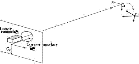
[0051] This method uses a fixed camera and a laser rangefinder to form a measurement unit. The two measurement units are installed on their respective rigid bodies, and innovatively measure the relative pose changes between the rigid bodies by looking at each other. The laser rangefinder The instrument is used to measure the translation vector between two rigid bodies with high precision, and the camera is used to measure the angle change between two rigid bodies. A closed loop of relative pose change measurement is formed by using the measurement units to shoot each other, which effectively improves the relative pose change measurement accuracy between two rigid bodies. This method does not require the coordinates of fixed markers to be known in advance, but directly calculates the relative deformation through the increment of image coordinates of two or more marker points, which is simple and efficient. The invention can be used for real-time measurement of relative pose cha...


PUM


Abstract

The invention mainly utilizes the advantages of the shooting measurement and laser ranging technology: high precision, simpleness and quickness to measure the relative pose change between two rigid bodies. The relative pose change measuring method based on eye-to-eye shooting measurement and laser ranging utilizes fixedly-connected cameras and laser range finders to form measuring units, wherein the two measuring units are respectively arranged on the respective rigid bodies, and can shoot the relative pose change between the rigid bodies through a mutual eye-to-eye shooting mode. The measuring method utilizes the mutual shooting mode of the measuring units to form a closed loop for the relative pose change measurement, so that the measurement precision for the relative pose change between the two rigid bodies can be effectively improved. The measuring method has no need for knowing about the coordinates of fixedly-connected markers in advance, and can resolve the relative deflection directly through the increment for image coordinates of two and more than two marker points, so that the measuring method is simple and efficient. The measuring method can be used for real-time measurement of the relative pose change between the rigid bodies, and has important theoretical research significance and is wide in the application prospect.

Description

technical field [0001] The invention mainly uses the high-precision, simple and fast advantages of camera measurement and laser ranging technology to measure the relative pose change between two rigid bodies. Background technique [0002] With the development of science and technology, the demand for measuring relative pose changes in various fields is becoming more and more urgent. For example, due to factors such as hull deformation, ground subsidence, and external forces, the relative deformation between the rigid body bases will affect the relative deformation of the rigid body bases. The measurement accuracy of the measuring equipment. Therefore, the development of a high-precision, stable and automatic relative pose change measurement system has important theoretical significance and application value. [0003] In recent years, the relative pose change measurement method based on computer vision technology has developed rapidly. The monocular pose estimation algorith...

Claims


Application Information

Patent Timeline
Patent Type & Authority Patents(China)
IPC IPC(8): G01B11/16
CPCG01B11/16
Inventor 孙祥一关棒磊傅丹孙澜琼
Owner NAT UNIV OF DEFENSE TECH
Learn More