Telegraph-pole centering device of electric power system

A power system and centralizer technology, applied in the field of power system pole centralizers, can solve problems such as low efficiency, centralization failure, time-consuming and labor-intensive problems

Inactive Publication Date: 2016-03-30
STATE GRID SHANDONG ELECTRIC POWER COMPANY WEIFANG POWER SUPPLY +1
View PDF13 Cites 6 Cited by
  • Summary
  • Abstract
  • Description
  • Claims
  • Application Information

AI Technical Summary

Problems solved by technology

If the pole tilts during this process, it will be very difficult to straighten the pole. The reasons are as follows: When the pole is straightened, it must occupy the ground space on the upright side. Then, 1. If the earth and rocks in this space are not cleared, then It is necessary to forcefully squeeze the soil and rock, and the required external force is extremely large. Generally, construction machinery, such as cranes, bulldozers, etc., must be used. If the soil and rocks in the space are completed by manually operating the shovel, firstly, the soil and rocks on the surface are relatively hard, and it is difficult to dig with the shovel. Secondly, for the convenience of digging with the shovel, a relatively large amount of upper layer of soil and rock must be dug out before the lower layer of soil and rock can be deeply excavated. Excavating the space on the upright side of the pole is conical with a large upper end and a smaller lower end, so it is time-consuming, labor-intensive, and inefficient. If it is completed by construction machinery such as excavators, there will be problems due to terrain, traffic restrictions, and unbalanced erection costs. high problem
[0005] The invention patents with Chinese patent numbers 201220200863.X and 201220222955.8 disclose two positive rod devices. These positive rod devices use the jacking force of the hydraulic lifting device (jack) to carry out strong righting and have a certain righting effect, but there are the following Disadvantages: 1. It does not have the function of cleaning up the soil and rocks on the upright side of the pole. By pulling hard to straighten the pole, it has a certain effect on those new poles that are newly put into use with a stable structure, but for those old poles that have been used for many years As far as the pole is concerned, it is easy to break the pole during the righting process; 2. Since the poles are generally erected in the wilderness, it is not only difficult for large-scale construction machinery to enter, but also greatly increases the cost of righting, so the earth and rock excavation work around the pole is generally It is done manually by multiple workers in turn using tools such as shovels and picks, which is not only time-consuming and laborious, but also produces a lot of dust when digging dry and hard earth and rocks, which is not conducive to the health of workers; 3. Since the weight of the pole is much larger than the bottom of the jack The weight of the straight nails and the fixing effect of the submerged part of the electric pole are much greater than the fixing effect of the submerged part of the electric pole, and the soil becomes hard. If the earth and rocks on the right side of the electric pole are not excavated, only the bottom of the jack will appear 4. The two positive rod devices used are locked with the electric pole through the hoop (clip), and the analysis of the force of the hoop (clip) shows that the hoop (clip) is affected by the jack The acting force can be divided into the upward force along the pole and the force in the righting direction of the pole. The force in the righting direction of the pole has the effect of righting the pole, but because the poles are all conical columns with thinner upper ends and thicker lower ends , so the upward force along the pole will push the hoop (clip) to the thinner end of the pole. Once the upward force along the pole is greater than the friction between the inner wall of the hoop (clip) and the outer wall of the pole, The hoop (clip) will inevitably slip off along the pole, resulting in failure of righting

Method used


Image

  • Telegraph-pole centering device of electric power system
  • Telegraph-pole centering device of electric power system
  • Telegraph-pole centering device of electric power system

Examples


Embodiment Construction

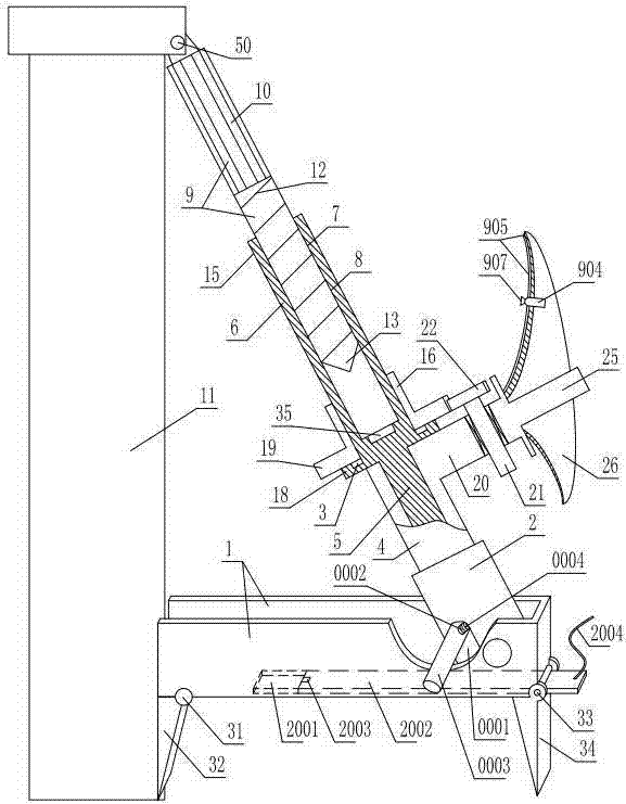
[0025] As shown in the figure, the power system pole centralizer includes a base 1 arranged horizontally. The longitudinal section of the base is U-shaped. front limit device. A swing tube 2 capable of swinging back and forth is hinged in the support section of the base, and a support sleeve 4 is inserted into the swing tube. An inner rotating shaft 5 that can only rotate coaxially relative to the support sleeve is installed in the support sleeve. The upper end of the inner rotating shaft is coaxially fixed with an inner cylinder 6 extending out of the support sleeve. The inner cylinder inner wall is uniformly provided with an axially extending inner cylinder straight groove 7. Slot 8. It also includes a multi-purpose shaft 9 that is inserted and matched with the inner cylinder. The upper ring of the upper half of the peripheral wall of the multi-purpose shaft is provided with a shaft straight tooth 10 that is inserted and matched with the straight groove of the inner cylind...


PUM


Abstract

The invention discloses a telegraph-pole centering device of an electric power system. The telegraph-pole centering device comprises a transversely-arranged base. A back limiting device and a front limiting device are arranged at the two ends of the base. A swinging barrel capable of swinging back and forth is hinged to the interior of a supporting section of the base. A supporting device is inserted into the swinging barrel and locked to the upper middle section of a telegraph pole through a hinged locking device capable of vertically swinging. The power input end of the supporting device is in transmission connection with a power device through a bendable transmission hose. A handle is further fixedly arranged on a supporting base. An outwards-extending protective cover is fixedly arranged at the inner end of the handle. The telegraph-pole centering device has the advantages that soil and stone on the normal-position side of the telegraph pole can be rapidly excavated, dust disoperation can be prevented, the telegraph pole can be rapidly centered, time and labor are saved, fixing is firm, the size is small, carrying is convenient, one person can independently center the telegraph pole, centering efficiency is high, and the telegraph pole can be prevented from being broken off.

Description

technical field [0001] The invention relates to a power system pole centralizer. Background technique [0002] Low-voltage overhead lines are lines used by residents and agricultural production. Most low-voltage overhead lines are supported by cement poles. When the cement pole is erected, it is generally hoisted and straightened by a crane, and the erection is very simple. Because the soil is soft when the poles are first installed, the poles during erection often tilt. This leads to the fact that the crane can only erect the second pole after one pole is completely erected, so the erection efficiency is low. For example, the pole centralizer whose Chinese patent number is 201320216893.4 is designed for hoisting electric poles. [0003] After the cement pole is installed, due to factors such as seasonal changes, geological conditions, and operating time, the cement pole is often skewed, which seriously threatens the normal operation of the power distribution line, so it i...

Claims


Application Information

Patent Timeline
IPC IPC(8): E04H12/34
CPCE04H12/34
Inventor 李玉志林勇吴金玉晋飞夏广祥李世贤王君安刘贯红杨君仁辛翠芹陈晓东唐敏刘晓亮刘忠辉卢晓惠卢怡含
Owner STATE GRID SHANDONG ELECTRIC POWER COMPANY WEIFANG POWER SUPPLY
Why Eureka
Try Eureka