Semi-automatic height-adjusting support and adjusting method thereof

A semi-automatic, height-adjusting technology, applied in bridge parts, bridges, buildings, etc., can solve the problems of low work efficiency, limited operation space, inconvenient operation, etc., and achieve the effect of high labor efficiency and low labor intensity.

Inactive Publication Date: 2016-03-30
中国人民解放军63926部队 +1
View PDF6 Cites 3 Cited by
  • Summary
  • Abstract
  • Description
  • Claims
  • Application Information

AI Technical Summary

Problems solved by technology

The currently used height-adjusting support includes an upper seat plate, a ball core, a middle seat plate, and a lower seat plate. The lower seat plate and the middle seat plate are threaded, and the lower seat plate is fixed on the foundation. When adjusting the height of the support, the operator clamps the twisting protrusion with a tool. The above-mentioned height adjustment support has the following defects: First, during the height adjustment process, due to the rotation of the middle seat plate, the ball core deviates from the , the damage to the spherical skateboard will affect the function and service life of the support; secondly, when adjusting the height, the support in the process of use is raised, the support is located between the lower beam and the foundation, and some supports have only one The surface is exposed, the operating space is limited, and the operation is inconvenient; third, because the middle seat plate rotates when the height is adjusted, the top of the middle seat plate must be circular, and no shock absorber can be installed between the middle seat plate and the upper seat plate. The spring does not have a shock absorption effect, but only has an anti-seismic effect; Fourth, in the process of height adjustment, multiple adjustments and multiple measurements are required, and the work efficiency is low

Method used


Image

  • Semi-automatic height-adjusting support and adjusting method thereof
  • Semi-automatic height-adjusting support and adjusting method thereof

Examples


Embodiment Construction

[0023] The structure and operating principle of the semi-automatic height-adjusting support of the present invention will be further described in detail below in conjunction with the accompanying drawings and specific embodiments.

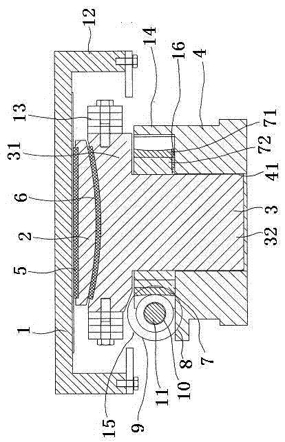
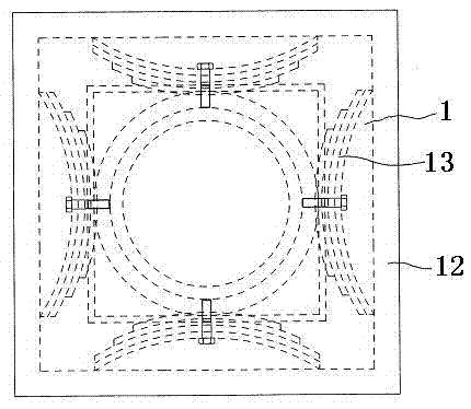
[0024] like figure 1 , 2 As shown, the semi-automatic height-adjusting support of the present invention includes an upper seat plate 1, a ball core 2, a middle seat plate 3 and a lower seat plate 4 at the upper end, and a plane slide plate 5 is arranged between the ball core 2 and the upper seat plate 1. A spherical slide 6 is arranged between the seat plate 3 and the ball core 2. The middle seat plate 3 includes a top plate 31 at the upper end and a column 32 at the lower end. There is a column hole 41 in the center of the lower seat plate 4, and the column 32 is inserted into the column hole 41. A turbine 7 and a worm 8 matched with the turbine 7 are arranged on the outside of the column 32 above the column hole 41. The turbine 7 is screwed to t...


PUM


Abstract

The invention belongs to the technical field of supports for buildings or bridges and adjusting methods thereof and discloses a semi-automatic height-adjusting support and an adjusting method thereof. The support is mainly and technically characterized by comprising an upper seat plate at the upper end, a spherical core, a middle seat plate and a lower seat plate, wherein a planar sliding plate is arranged between the spherical core and the upper seat plate, a spherical sliding plate is arranged between the middle seat plate and the spherical core, the middle seat plate comprises a top plate at the upper end and a stand column at the lower end, the center of the lower seat plate is provided with a stand column hole, the stand column is inserted into the stand column hole, a worm gear and a worm matched with the worm gear are arranged on the outer side of the part, above the stand column hole, of the stand column, the worm gear and the stand column are in threaded connection, worm brackets are arranged at the two ends of the worm, the worm is connected with the worm brackets through bearings, each worm bracket is provided with a crank insertion hole, and a crank is inserted in the crank insertion holes. In the installing process, the side where the crank insertion holes are formed is turned outwards, the number of rotation circles required for the worm is calculated according to a measured result first, and then the crank is rotated according to a calculated result and adjusted accurately in place at a time; in this way, labor intensity is low, and labor efficiency is high.

Description

technical field [0001] The invention belongs to the technical field of a support for buildings or bridges and an adjustment method thereof, and in particular relates to a semi-automatic height-adjusting support and an adjustment method thereof. Background technique [0002] In the field of buildings or bridges, due to the subsidence of the foundation and the different loads on the buildings or bridges, the bearings are unevenly stressed, which not only affects the stability and service life of the buildings or bridges, but also easily causes some bearings to have too much bearing capacity. causing damage. In order to solve the problems referred to above, people adopt the support that can be adjusted in height. The currently used height-adjusting support includes an upper seat plate, a ball core, a middle seat plate, and a lower seat plate. The lower seat plate and the middle seat plate are threaded, and the lower seat plate is fixed on the foundation. When adjusting the he...

Claims


Application Information

Patent Timeline
Patent Type & Authority Applications(China)
IPC IPC(8): E04B1/36E01D19/02
Inventor 刘宏扬雷逢胜刘炜王立志杜峰峰付国社肖海文蔡亦农蔺旭宏
Owner 中国人民解放军63926部队
Why Eureka
Try Eureka