
A vibration quality detection system and method

A vibration quality and detection system technology, applied in the direction of measuring devices, measuring ultrasonic/sonic/infrasonic waves, instruments, etc., can solve problems such as low efficiency, low automation of vibration industry quality inspection, and difficulty in data aggregation

Active Publication Date: 2018-12-21
SHENZHEN YATEKS OPTICAL ELECTRONICS TECH CO LTD
View PDF7 Cites 0 Cited by
  • Summary
  • Abstract
  • Description
  • Claims
  • Application Information

AI Technical Summary

Problems solved by technology

[0003] The technical problem to be solved by the present invention is to solve the problems of low automation, low efficiency, low accuracy, and difficulty in gathering data to form testing standards in vibration industry quality testing

Method used


Image

  • A vibration quality detection system and method
  • A vibration quality detection system and method
  • A vibration quality detection system and method

Examples


Embodiment 1

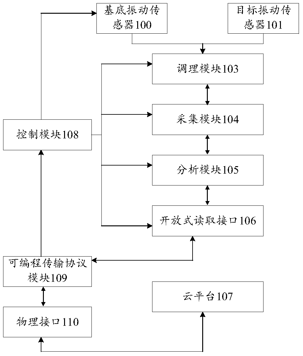
[0035] Such as figure 1 As shown, the embodiment of the present invention provides a vibration quality detection system, the system includes:

[0036] The base vibration sensor 100 is used for background vibration subtraction. The base vibration sensor 100 is installed on the base of the vibration assembly test bench on the target detection product production line, and the base vibration sensor 100 can be installed on multiple channels for background vibration subtraction.

[0037] The target vibration sensor 101 is used to measure the vibration of the target object. The target vibration sensor 101 is installed on the vibration part of the target detection product, and the target vibration sensor 101 can be set on multiple channels for measuring the vibration of the target object. For example, when the target detection product is an air conditioner, the The target vibration sensor 101 is placed at the welded elbow of the air-conditioning copper pipe, because this place is a ...

Embodiment 2

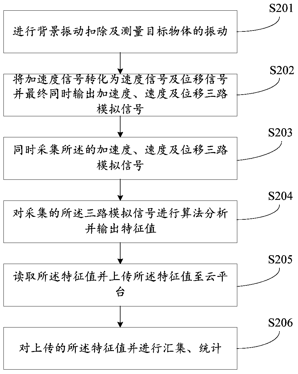
[0050] Such as figure 2 As shown, the embodiment of the present invention provides a vibration quality detection method, the method includes the following steps:

[0051] S201, performing background vibration subtraction and measuring the vibration of the target object.

[0052] S202, converting the acceleration signal into a velocity signal and a displacement signal, and finally outputting three analog signals of acceleration, velocity and displacement at the same time.

[0053] S203. Simultaneously collect the three analog signals of acceleration, velocity and displacement.

[0054] S204. Perform algorithmic analysis on the three analog signals collected and output feature values.

[0055] S205. Read the characteristic value and upload the characteristic value to the cloud platform.

[0056] S206. Collect and count the uploaded feature values.

[0057] The background vibration is subtracted by the base vibration sensor, and the vibration of the target object is measured...


PUM


Abstract

The invention relates to a vibration measurement field, and discloses a vibration quality detection system and method. The system comprises a substrate vibration sensor, an object vibration sensor, a conditioning module, a collection module, an analysis module, an open reading interface, a cloud platform, a control module, a programmable transmission protocol module and a physical interface. The vibration quality detection system and method can cooperate with the rhythm of a production line, and intelligently, efficiently and accurately complete the quality detection of a target detection product, and are intelligent and automatic; in addition, the system and device can upload characteristic values to be detected to the cloud platform for collection and statistics, thereby facilitating data accumulation for setting a detection standard.

Description

【Technical field】 [0001] The invention relates to the field of vibration measurement, in particular to a vibration quality detection system and method. 【Background technique】 [0002] The international community is entering the era of Industry 4.0, and China is actively building Made in China 2025. In the face of increasing labor costs, manufacturers such as air conditioners that need to inspect the vibration quality of their products urgently need a highly intelligent and automated vibration quality inspection system and method, which can match the rhythm of the production line, automatically and efficiently , Accurately complete the quality inspection. At present, the vibration quality inspection mainly adopts simple hand-held vibration measuring instruments to measure the basic value of vibration, manually touch with hands, and listen with ears to identify the quality. The efficiency is very low and it is impossible to build an automated test production line, resulting i...

Claims


Application Information

Patent Timeline
Patent Type & Authority Patents(China)
IPC IPC(8): G01H11/08
CPCG01H11/08
Inventor 马天悦曾佳李传刚陈桂东张盛波张志涛邹海娟许利红
Owner SHENZHEN YATEKS OPTICAL ELECTRONICS TECH CO LTD
Learn More