Delivery window applied to clean room

A technology of clean room and transfer window, applied in the field of transfer window, can solve the problems of air circulation and pollution of clean room, etc., and achieve the effect of avoiding air communication and simple structure.

Active Publication Date: 2016-03-23
ZHEJIANG CHUANGJIE PAPER
View PDF6 Cites 2 Cited by
  • Summary
  • Abstract
  • Description
  • Claims
  • Application Information

AI Technical Summary

Problems solved by technology

A common transfer window is a rectangular box. The two ends of the box are connected and installed on the wall of the clean room, connecting the clean room and the outside world. The outlets at both ends of the box are respectively equipped with doors and windows, and door and window sealing boxes In order to achieve isolation, the doors and windows of the existing transfer windows are generally opened and closed manually, and sometimes it is due to the negligence of the staff that they forget to close the corresponding doors and windows when transferring goods, which will easily cause air circulation between the clean room and the outside world, thereby polluting the clean room

Method used


Image

  • Delivery window applied to clean room
  • Delivery window applied to clean room
  • Delivery window applied to clean room

Examples


Embodiment Construction

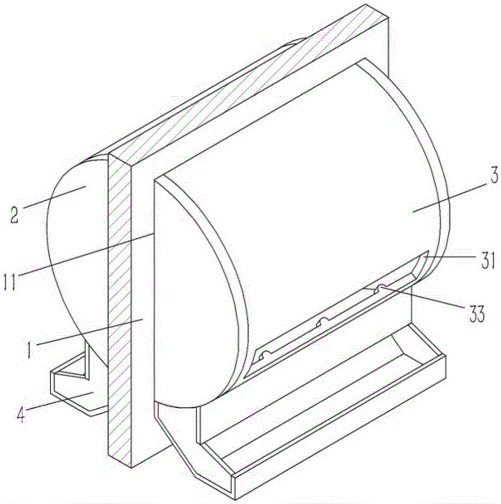
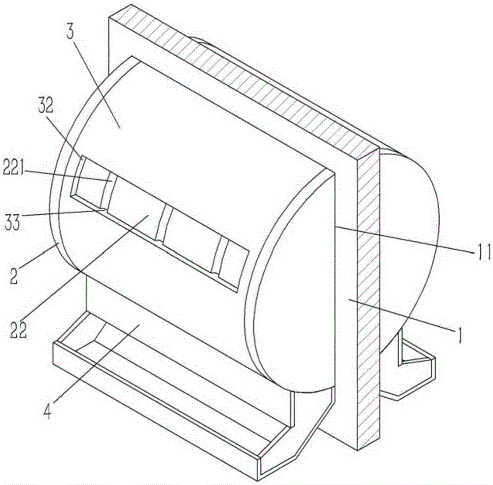
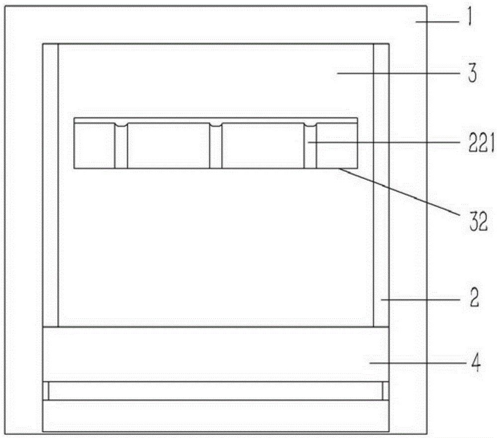
[0015] Example: see Figures 1 to 4 As shown, a transfer window applied to a clean room includes a wall 1 of the clean room, a window 11 is formed on the wall 1, and two fixing discs 2 are inserted into the window 11, and the fixing discs 2 are fixed on the side of the window 11 Above, there is an arc-shaped cylinder 22 between the fixed disks 2, and the two ends of the cylinder 22 are formed on the two fixed disks 2, and the sleeve 3 is inserted on the cylinder 22, and the two ends of the cylinder sleeve 3 are against the On the fixed plate 2, fan-shaped inlets 31 and outlets 32 are respectively formed on both sides of the sleeve 3, and several guide blocks 33 are formed on the inner wall of the sleeve 3 on the upper and lower sides of the outlet 32 ​​and the inlet 31, and on the outer wall of the cylinder 22 A plurality of guide grooves 221 are formed, the two ends of the guide grooves 221 run through the two sides of the cylinder 22, the guide block 33 of the sleeve 3 is in...


PUM


Abstract

The invention discloses a delivery window applied to a clean room. The delivery window comprises a wall of the clean room. A window body is formed in the wall. Two fixing discs are inserted in the window body and fixed to the sides of the window body. An arc-shaped cylinder is arranged between the fixing discs. The two ends of the cylinder are formed on the two fixing discs. The cylinder is inserted in a barrel sleeve in a sleeved manner. The two ends of the barrel sleeve abut against the fixing discs. A sector-shaped inlet and a sector-shaped outlet are formed in the two sides of the barrel sleeve respectively. Multiple guide blocks are formed at the portions, on the upper sides and the lower sides of the outlet and the inlet, on the inner wall body of the barrel sleeve. Multiple guide grooves are formed in the outer wall body of the cylinder. The two ends of each guide groove penetrate the two sides of the cylinder. The guide blocks of the barrel sleeve are inserted in the corresponding guide grooves of the cylinder. The inner wall body and the outer wall body, on the lower side of the barrel sleeve, of the wall are fixedly connected with material receiving groove boxes respectively. The delivery window is simple in structure, small objects can be delivered in and out of the clean room conveniently, meanwhile the clean room and the external environment can be isolated all the time in the delivery process, and the clean room is prevented from being communicated with external air.

Description

Technical field: [0001] The invention relates to the technical field of purification devices, in particular to a transfer window applied to a clean room. Background technique: [0002] The transfer window is a channel structure used in hospitals, clean rooms and other places to facilitate the transfer of small goods. It can isolate two rooms or one room from the air communication with the outside world when transferring goods, such as isolating clean rooms and clean rooms. The outside world, to prevent the outside air from polluting the clean room. A common transfer window is a rectangular box. The two ends of the box are connected and installed on the wall of the clean room, connecting the clean room and the outside world. The outlets at both ends of the box are respectively equipped with doors and windows, and door and window sealing boxes In order to achieve isolation, the doors and windows of the existing transfer windows are generally opened and closed manually. Someti...

Claims


Application Information

Patent Timeline
Patent Type & Authority Applications(China)
IPC IPC(8): B65G29/00
CPCB65G29/00B65G2207/26
Inventor 冯义文
Owner ZHEJIANG CHUANGJIE PAPER
Why Eureka
Try Eureka