Tapping processing positioning fixture

A technology for positioning fixtures and positioning blocks, which is applied to manufacturing tools, metal processing equipment, tangent devices, etc., can solve the problems affecting the working efficiency and quality of tapping processing, low fixture connection efficiency, and decreased positioning accuracy. The dismantling operation is flexible and convenient, improving work efficiency and quality, and reducing the effect of structural wear

Active Publication Date: 2016-03-23
PERLMAN ELECTRICAL KUSN
View PDF5 Cites 1 Cited by
  • Summary
  • Abstract
  • Description
  • Claims
  • Application Information

AI Technical Summary

Problems solved by technology

[0002] At present, in the processing of some workpieces, it is often necessary to perform tapping operations on the workpiece through tapping equipment, but in actual use, it is found that when the current workpiece is performing tapping operations, it is first necessary to fix the workpiece on the tapping processing equipment through a fixture On the one hand, the tapping process can then be carried out, but because the current tapping fixture structure often adopts the traditional threaded connection structure, on the one hand, the connection efficiency of the fixture is low when it is connected to the tapping equipment, and on the other hand On the one hand, in long-term use, it is very easy for the outlet fixture to drop in positioning accuracy due to the wear of the connecting thread. In severe cases, the fixture may even be scrapped, which seriously affects the working efficiency and quality of tapping processing, and causes a large waste of resources. Therefore, In response to this current situation, it is urgent to develop an inventive tapping fixture device to meet the needs of actual production and use

Method used


Image

  • Tapping processing positioning fixture

Examples


Embodiment Construction

[0011] In order to make the technical means, creative features, goals and effects achieved by the present invention easy to understand, the present invention will be further described below in conjunction with specific embodiments.

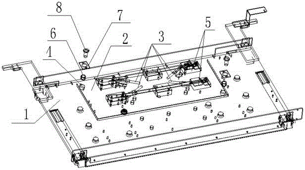
[0012] Such as figure 1 The described positioning fixture for tapping processing includes a tapping machine base plate 1, a product positioning base 2, a product positioning block group, a detection sensor 3, a quick positioning pin shaft system, a tapping machine base plate 1 and a product positioning base 2 At least four positioning holes 4 are arranged on the top, the tapping machine base plate 1 and the product positioning base 2 are distributed parallel to each other, and the positioning holes 4 of the tapping machine base plate 1 and the product positioning base 2 are distributed in correspondence with each other, and the tapping machine base plate 1 and the product positioning base 2 are connected by at least two quick positioning pin shaft...


PUM


Abstract

The invention relates to a tapping processing positioning fixture which comprises a tapping machine baseplate, a product positioning base, a product positioning block group, testing sensors and quick positioning pin shaft systems, wherein at least four positioning holes are formed in each of the tapping machine baseplate and the product positioning base; the tapping machine baseplate and the product positioning base are connected through at least two quick positioning pin shaft systems; the quick positioning pin shaft systems are mounted in the positioning holes; the product positioning block group comprises at least three positioning blocks; each quick positioning pin shaft system comprises guide sleeves, a positioning pressing plate and a positioning pin shaft. On one hand, the positioning precision and the mounting and positioning speed in the workpiece tapping processing operation process can be effectively improved, and on the other hand, the use stability of the fixture equipment can be effectively improved and the structure abrasion of the fixture equipment in the use process can be reduced.

Description

technical field [0001] The invention relates to a fixture device, in particular to a positioning fixture for tapping processing. Background technique [0002] At present, in the processing of some workpieces, it is often necessary to perform tapping operations on the workpiece through tapping equipment, but in actual use, it is found that when the current workpiece is performing tapping operations, it is first necessary to fix the workpiece on the tapping processing equipment through a fixture On the one hand, the tapping process can then be carried out, but because the current tapping fixture structure often adopts the traditional threaded connection structure, on the one hand, the connection efficiency of the fixture is low when it is connected to the tapping equipment, and on the other hand On the one hand, in long-term use, it is very easy for the outlet fixture to drop in positioning accuracy due to the wear of the connecting thread. In severe cases, the fixture may eve...

Claims


Application Information

Patent Timeline
IPC IPC(8): B23G1/44
CPCB23G1/44
Inventor 马世成
Owner PERLMAN ELECTRICAL KUSN
Why Eureka
Try Eureka