Eureka AIR delivers breakthrough ideas for toughest innovation challenges, trusted by R&D personnel around the world.

A riveting machine for refrigerator side panels

A technology of a riveting machine and a riveting mechanism, which is applied in the field of riveting machines for refrigerator side panels, can solve the problems of inability to meet the processing requirements of workpieces of different sizes, inability to realize one-time riveting and riveting tasks, etc., and achieves high riveting efficiency, simple structure and rapid riveting Effect

Active Publication Date: 2017-10-13
JIANGSU HENGHAO ELECTROMECHANICAL MFG
View PDF6 Cites 1 Cited by
  • Summary
  • Abstract
  • Description
  • Claims
  • Application Information

AI Technical Summary

Problems solved by technology

During the processing of refrigerator side panels, traditional riveting machines are generally used to meet the connection requirements through single-point or multiple riveting means on a plane, so it is impossible to complete all riveting tasks in one riveting
And in the use of traditional riveting machines, positioning tooling is generally used. Traditional positioning tooling can only meet workpieces of one size, and cannot meet the processing requirements of workpieces of different sizes.

Method used


Image

  • A riveting machine for refrigerator side panels
  • A riveting machine for refrigerator side panels
  • A riveting machine for refrigerator side panels

Examples


Embodiment Construction

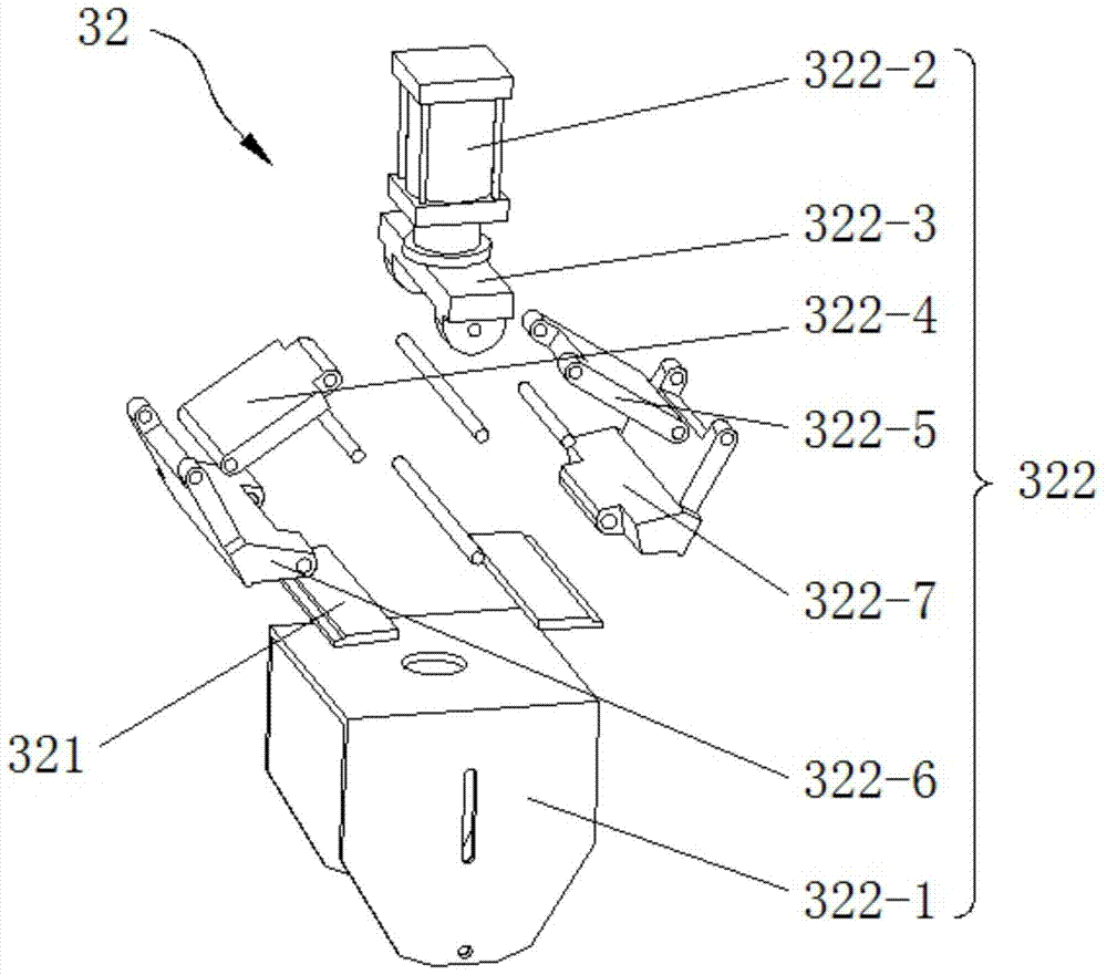
[0027] See Figure 1 to Figure 5 , the present invention includes a frame 1, a workbench 2 and a riveting mechanism 3; the workbench 2 is fixedly arranged on the frame 1; There is a positioning frame 4 for placing workpieces; the riveting mechanism 3 includes a lifting device 31 and a riveting device 32;

[0028] The lifting device 31 includes a lifting plate 311, a base 312 and a lifting cylinder 313; the lifting cylinder 313 is fixedly arranged on the base 312; the lifting plate 311 is dynamically arranged on the base 312; the lifting cylinder 313 The telescopic rod is fixedly connected with the lifting plate 311; the riveting device 32 is fixedly arranged on the lifting plate 311;

[0029] The riveting device 32 includes a riveting jig 321 and a closing driving assembly 322 for driving the riveting jig 321 to close; the riveting jig 321 is fixedly arranged on the closing driving assembly 322 .

[0030] The closing drive assembly 322 includes a bracket 322-1, a riveting cy...


PUM


Abstract

The invention relates to a riveting machine for a refrigerator side plate. The riveting machine comprises a rack, a workbench and riveting mechanisms, wherein the workbench is fixedly arranged on the rack; the riveting mechanisms are symmetrically arranged at the two sides of the workbench; a positioning frame for placing a workpiece is arranged on the workbench; each riveting mechanism comprises a lifting device and a riveting device; each riveting device comprises a lifting plate, a pedestal and a lifting air cylinder; each lifting air cylinder is fixedly arranged on the pedestal; each lifting plate is arranged on the pedestal in a sliding mode; a telescopic pole of each lifting air cylinder is fixedly connected with the corresponding lifting plate; each riveting device is fixedly arranged on the corresponding lifting plate; each riveting device comprises a riveting clamp and a closing drive assembly for driving the riveting clamp to close; and each riveting clamp is fixedly arranged on the corresponding closing drive assembly. The riveting machine can meet the requirements of simultaneously riveting at multiple positions, realizes quick riveting and greatly improves production efficiency.

Description

technical field [0001] The invention relates to a riveting machine, in particular to a riveting machine for refrigerator side panels. Background technique [0002] Riveting machine, also known as riveting machine, riveting machine, etc., is a mechanical device that uses rivets to rivet items according to the principle of cold rolling. The traditional riveting machine is driven by pneumatic, oil pressure or electric, and realizes the riveting process of a single place or multiple places on a plane through a punch. [0003] The side panels of the refrigerator are formed by connecting multiple panels through a riveting process. During the processing of refrigerator side panels, traditional riveting machines are generally used to meet the connection requirements through single-point or multiple riveting means on a plane, so it is impossible to complete all riveting tasks in one riveting. Moreover, positioning tooling is generally used in the use of traditional riveting machine...

Claims


Application Information

Patent Timeline
Patent Type & Authority Patents(China)
IPC IPC(8): B21J15/10B21J15/30B21J15/38
CPCB21J15/10B21J15/30B21J15/38
Inventor 韩志兵周荣林
Owner JIANGSU HENGHAO ELECTROMECHANICAL MFG
Why Eureka
Eureka Blog
Learn More