
Turning roller path for direct rolling of multi-strand continuous casting slab

A multi-strand continuous casting and continuous casting slab technology, which is applied in the direction of metal rolling, metal rolling, manufacturing tools, etc., can solve the problem of deviation between the continuous casting billet line and the rolling line, so as to shorten the transportation distance and reduce the heat The effect of fast loss and blank transfer speed

Inactive Publication Date: 2016-03-23
WISDRI ENG & RES INC LTD
View PDF8 Cites 12 Cited by
  • Summary
  • Abstract
  • Description
  • Claims
  • Application Information

AI Technical Summary

Problems solved by technology

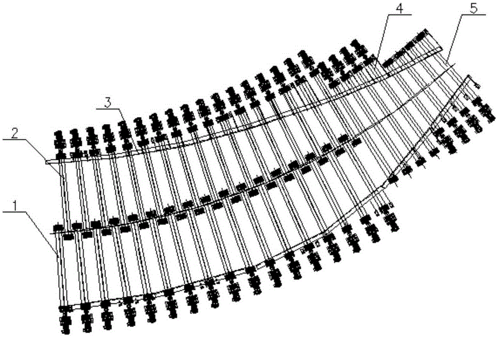
[0004] The main purpose of the present invention is to provide a turning roller table for direct rolling of multi-strand continuous casting slabs, which aims to solve the problem of deviation and height difference between the continuous casting billet line and rolling line due to site problems, and meet the requirements of continuous casting billets. drop shipping demand

Method used


Image

  • Turning roller path for direct rolling of multi-strand continuous casting slab
  • Turning roller path for direct rolling of multi-strand continuous casting slab
  • Turning roller path for direct rolling of multi-strand continuous casting slab

Examples


Embodiment Construction

[0022] It should be understood that the specific embodiments described here are only used to explain the present invention, not to limit the present invention.

[0023] It should be noted that, in the description of the present invention, the terms "horizontal", "vertical", "upper", "lower", "front", "rear", "left", "right", "vertical", The orientation or positional relationship indicated by "horizontal", "top", "bottom", "inner", "outer", etc. is based on the orientation or positional relationship shown in the drawings, and is only for the convenience of describing the present invention and simplifying the description, and It is not to indicate or imply that the device or element referred to must have a particular orientation, be constructed in a particular orientation, or operate in a particular orientation, and thus should not be construed as limiting the invention. In addition, the terms "first", "second", etc. are used for descriptive purposes only, and should not be cons...


PUM


Abstract

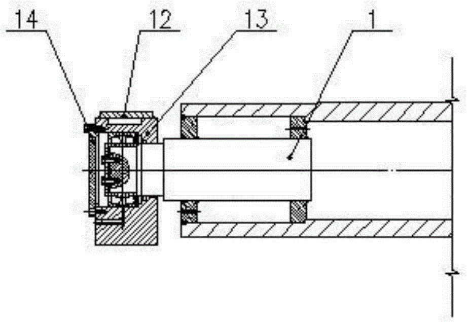
The invention discloses a turning roller path for direct rolling of a multi-strand continuous casting slab. The turning roller path comprises a plurality of conical rollers, a bearing seat which is arranged below the conical rollers and supports the conical rollers, a base which is arranged below the bearing seat and supports the bearing seat, a drive mechanism which is fixedly connected with the conical rollers and drives the conical rollers to rotate and a heat preservation cover which is arranged above the conical rollers in a covering manner, wherein the conical rollers are arranged in a manner of turning while climbing in the flowing direction of a continuous casting slab so as to form an arc-shaped roller path; and the conical rollers at the inlet of the arc-shaped roller path are arranged in a crossed manner. The turning roller path for direct rolling of the multi-strand continuous casting slab solves the problems about deviation and height difference of a continuous casting slab outlet line and a rolling line caused by a place and meets the demand for directly sending the continuous casting slab.

Description

technical field [0001] The invention relates to the technical field of steelmaking production equipment, in particular to a turning roller table for direct rolling of multi-strand continuous casting slabs. Background technique [0002] The direct rolling of continuous casting slab means that the continuous casting slab is not heated by a heating furnace, and after being supplemented by a corner heating device during transportation, it is directly sent to a rolling mill for rolling or directly sent to a rolling mill for rolling. It can not only greatly reduce energy consumption, shorten the production cycle of products, but also increase the metal yield, and at the same time reduce the floor area of ​​the factory building and save investment. Because of its direct economic and social benefits, it is used more and more widely. [0003] However, the continuous casting billet line and the steel rolling line are often not on a straight line, and there is a height difference at t...

Claims


Application Information

Patent Timeline
Patent Type & Authority Applications(China)
IPC IPC(8): B21B1/46B21B39/02
CPCB21B1/463B21B39/02
Inventor 王清秀闵威范锦龙
Owner WISDRI ENG & RES INC LTD
Learn More