
Radioactive particle implanting gun

A technology of radioactive particles and gun body, applied in the field of medical devices, can solve problems such as waste of resources and funds, and achieve the effects of easy concentration, convenient operation and simple structure

Active Publication Date: 2016-03-23
BEIJING ZHIBO BIO MEDICAL TECH +1
View PDF12 Cites 9 Cited by
  • Summary
  • Abstract
  • Description
  • Claims
  • Application Information

AI Technical Summary

Problems solved by technology

When the hospital is in use, it is necessary to equip various types of implant needles with various implant guns according to this situation, which virtually brings waste of resources and funds.

Method used


Image

  • Radioactive particle implanting gun
  • Radioactive particle implanting gun
  • Radioactive particle implanting gun

Examples


Embodiment 1

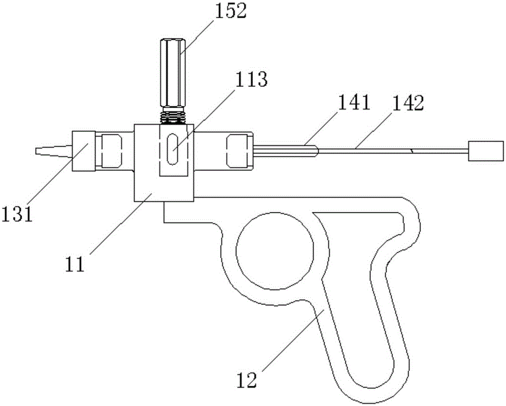
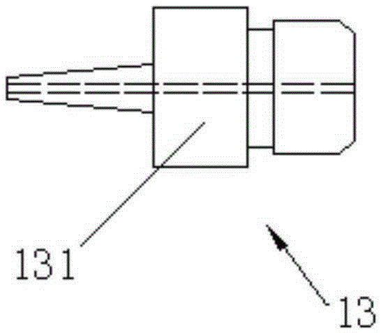
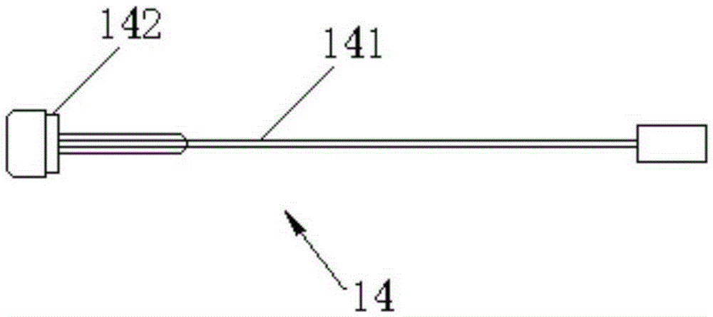
[0032] as attached Figure 1 to Figure 7 As shown, a radioactive particle implant gun according to the present invention includes a gun body 11, the gun body 11 is arranged on a handle 12, an adapter assembly 13 is provided at the front end of the gun body 11, and an adapter assembly 13 is provided at the rear end of the gun body 11. A push pin assembly 14 is provided, and a cavity 111 for fixing the clip assembly 15 is provided in the gun body 11. The side wall of the gun body 11 is provided with two holes that are all connected with the gun body 11, and the top of the gun body 11 is close to the gun body 11. Positioning pin 112 is provided in the hole of gun body 11 bottom, and positioning pin cover 113 for preventing positioning pin 112 from moving outwards is provided in the hole near gun body 11 bottom; Described positioning pin 112 is stepped positioning pin, and described positioning pin cover 113 It is L-shaped.

[0033] In this embodiment, the adapter assembly 13 and...

Embodiment 2

[0039] as attached Figure 8 , 9 As shown in , 10, the radioactive particle implant gun of the present invention provides a second embodiment, which differs from Embodiment 1 in that the adapter assembly 13 includes a second body 132, and the second body 132 is provided with Central hole and fixed shaft 133, the axis of the central hole is perpendicular to the space of the fixed shaft 133; and includes a buckle 134 that rotates with the center of the fixed shaft 133, and one end of the buckle 134 is provided with a sleeve assembly for fixing the push pin The other end of the buckle part 135 of 16 is provided with a buckle return spring body 136 for resetting the buckle 134 . Wherein, the push pin sleeve assembly 16 includes a sleeve 161 and a fixing portion 162 arranged at the end of the sleeve 161, the sleeve 161 is a hollow tube, and the sleeve 161 is used to accommodate the push pin 141, also serving as The delivery channel of particles; the fixing part 162 is used to coo...


PUM


Abstract

The invention relates to a radioactive particle implanting gun, which comprises a gun body, wherein the gun body is arranged on a handle; the front end of the gun body is provided with an adapter assembly; the back end of the gun body is provided with a push pin assembly; a cavity used for fixing a cartridge holder assembly is arranged in the gun body; and two holes penetrating through the gun body are formed in one side wall of the gun body, wherein a positioning pin is arranged in the hole near the top of the gun body; and a positioning pin cover is arranged in the hole near the bottom of the gun body. The radioactive particle implanting gun has the excellent effects that the adapter assembly, the gun body and the push pin assembly are designed into a whole; the problem that in the prior art, once alignment is needed when the push pin is pushed once, and then the insertion and the pulling out can be completed is solved; an operator can conveniently concentrate; meanwhile, the instrument compatibility is improved; all parts of the implanting gun are mutually independent; when the parts are damaged, only the damaged parts need to be replaced; the problem that the whole set of implanting equipment is scrapped in the prior art is solved; the structure is simple; the operation is convenient; and portability is realized.

Description

technical field [0001] The invention relates to the technical field of medical instruments, in particular to a radioactive particle implantation gun. Background technique [0002] Radioactive seed implantation therapy is a treatment method that implants a radioactive source inside the tumor and allows it to continuously release radiation to destroy the tumor. , Short-distance radiation, so that the tumor tissue suffers maximum damage, while normal tissue is not damaged or only slightly damaged. [0003] At present, the implantation of radioactive particles is done manually. Specifically, the implantation needle is inserted into the tumor site of the patient, and the head of the implantation needle is connected to the implantation needle interface of the implantation gun. The frontmost particles in the particle magazine are located in the trajectory of the implant gun, and the medical staff manually pushes and pulls the needle core along the trajectory to push the radioactiv...

Claims


Application Information

Patent Timeline
IPC IPC(8): A61M36/12
CPCA61N5/1007A61N5/1027A61N2005/1011A61N2005/1021
Inventor 林春平侯晓飞钟诚
Owner BEIJING ZHIBO BIO MEDICAL TECH
Learn More