
Time synchronization system based on intelligent substation video monitoring

A technology of intelligent substation and video surveillance, applied in closed-circuit television systems, radio-controlled timers, instruments, etc., can solve the problems of real-time time synchronization neglect, delay or time stop, no unified time synchronization, etc., and achieve network structure. Clear and simple, high reliability and stability, open and inclusive effect

Inactive Publication Date: 2016-03-16
ELECTRIC POWER RES INST STATE GRID JIANGXI ELECTRIC POWER CO +1
View PDF10 Cites 4 Cited by
  • Summary
  • Abstract
  • Description
  • Claims
  • Application Information

AI Technical Summary

Problems solved by technology

Through investigation, it is found that the video surveillance systems of smart substations currently in operation come from many different manufacturers at home and abroad, and they all operate independently without a unified time synchronization. or time stop, etc., which brings difficulties to fault inquiry and judgment
The reasons mainly include the following three aspects. First, the current video surveillance system is mainly concerned with the quality of image acquisition, response speed, and storage capacity, and there are varying degrees of neglect of real-time time synchronization.
The second is that the factory station equipment does not support time synchronization. According to the survey, the video surveillance of most factory stations does not meet the network time synchronization requirements. The manufacturer has not set up a network time synchronization interface or a time response module.
The third is that the master station system does not meet the network time synchronization requirements, and does not meet the NTP network time synchronization requirements

Method used


Image

  • Time synchronization system based on intelligent substation video monitoring
  • Time synchronization system based on intelligent substation video monitoring

Examples


Embodiment Construction

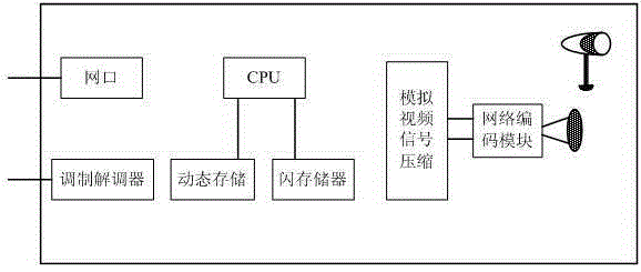
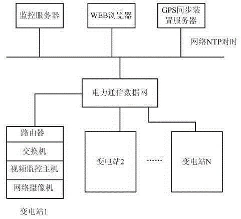
[0016] The present invention is specifically implemented on the intelligent substation video monitoring system, as shown in FIG. 1 .

[0017] In this embodiment, a time synchronization system based on intelligent substation video monitoring includes a video monitoring network server, a GPS time synchronization device, a WEB browsing server and an all-digital IPC system. The video monitoring network server, the GPS time synchronization device server and the WEB browsing server are connected to the power communication data network through the network; the video monitoring network server is installed with an NTP time synchronization protocol component, and is connected with the GPS time synchronization device server through the network. The video monitoring network server and WEB browsing server are used for monitoring, storing, managing and consulting the video images transmitted by each substation.

[0018] As shown in Figure 2, the front end of the IPC system is composed of a ...


PUM


Abstract

The invention discloses a time synchronization system based on intelligent substation video monitoring, which comprises a video monitoring network server, a WEB browsing server, a GPS time synchronization device and an all digital IPC system, wherein the all digital IPC system is arranged at an intelligent substation end, and through a high-speed communication data network, network NTP time synchronization is carried out; GPS time synchronization signals are received for the NTP time synchronization, the video monitoring network server is connected with the time synchronization device for network time synchronization, each timing device is provided with a time synchronization assembly in a unified mode, and a network time synchronization function is provided; and the intelligent substation supports NTP(SNTP) time synchronization based on an IEC61850 technology protocol, and through a network switch, time synchronization is directly carried out on an intelligent substation video monitoring host. The video acquisition monitoring time synchronization requirements are met, the time synchronization precision can reach an ms level, and the time synchronization problem existing in operation and monitoring of the intelligent substation can be solved.

Description

technical field [0001] The invention relates to a time synchronization system based on intelligent substation video monitoring, which belongs to the technical field of intelligent substation monitoring. Background technique [0002] With the expansion of the grid scale and the improvement of the automation level of power equipment, most smart substations have the four-remote function and realize unattended operation. However, after the substation is unattended, many problems have been caused, such as the failure of the more prominent automation communication network, the realization of remote control and safety issues, external damage and damage to substation equipment caused by human factors. Therefore, the substation remote video monitoring system is particularly important, that is, "remote viewing" technology. The video real-time monitoring system of the smart substation can remotely monitor environmental parameters other than power production to the maximum extent, so t...

Claims


Application Information

Patent Timeline
Patent Type & Authority Applications(China)
IPC IPC(8): H04N7/18G04R20/02
CPCH04N7/18G04R20/02
Inventor 熊丽霞邹进谢国强
Owner ELECTRIC POWER RES INST STATE GRID JIANGXI ELECTRIC POWER CO
Learn More