
A locking device for precision optical instruments

A locking device and precision optics technology, applied in the direction of fixing devices, threaded fasteners, connecting components, etc., can solve shaking or misalignment, the angle or relative displacement between the imaging device and the focal plane, and the axis deviation of the locked part and other problems, to achieve the effect of convenient operation, correct position and uniform locking force

Active Publication Date: 2017-12-05
NANJING ZHONGKE ASTROMOMICAL INSTR
View PDF4 Cites 0 Cited by
  • Summary
  • Abstract
  • Description
  • Claims
  • Application Information

AI Technical Summary

Problems solved by technology

After focusing, it must be locked with a locking device, otherwise factors such as vibration will easily cause shaking or misalignment, and the relative position of the imaging device and the focal plane will change, resulting in unclear imaging
[0003] At present, most of the locking devices of optical instruments rely on the locking screw to squeeze the locked part from one side, which often causes the axis of the locked part to shift, which in turn causes the shift of the focus position, the imaging device and the focus Angles or relative displacements occur between planes, resulting in partial or overall unclear imaging, and the target object deviates from the center of the image, etc.

Method used


Image

  • A locking device for precision optical instruments
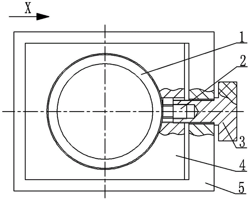
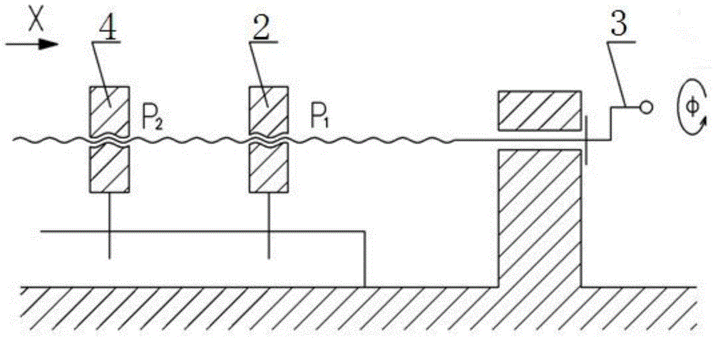
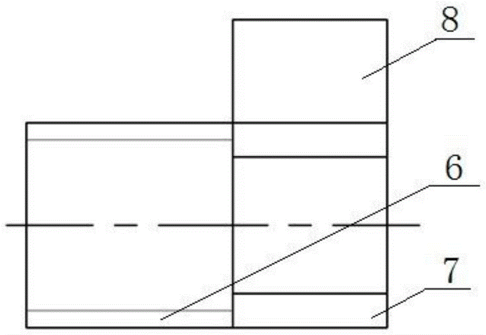
  • A locking device for precision optical instruments
  • A locking device for precision optical instruments

Examples


Embodiment Construction

[0022] The present invention will be described in further detail below in conjunction with the accompanying drawings and embodiments.

[0023] A preferred implementation structure of a locking device for precision optical instruments of the present invention is as follows: figure 1 As shown, it includes adjusting screw 3, locking block one 2, locking block two 4 and fixing block 5. The structure of adjusting screw 3 is as Figure 7 As shown, it includes a head cap part 12 and a threaded part 13. The threaded part 13 is provided with an internal thread and an external thread. The pitch of the internal thread and the external thread are the same and the direction of rotation is opposite. The head cap portion 12 is processed with knurling, and the structure of the locking block-2 is as follows: image 3 and Figure 4 As shown, it includes a head 6 and a tail 7 , and the head 6 is provided with an external thread matching the internal thread of the adjusting screw 3 . The stru...


PUM


Abstract

The invention discloses a locking device for a precise optical instrument. The locking device comprises an adjusting screw, a locking block I, a locking block II and a fixing block. The adjusting screw is provided with inner threads and external threads; the inner threads and the external threads are the same in thread pitch and different in screwing direction. The head part of the locking block I is provided with external threads matched with the inner threads of the adjusting screw; and the opening part of the locking block II is provided with inner threads matched with the external threads of the adjusting threads. The fixing block is fixed on the instrument and is used for guiding the locking block II. When the locking device disclosed by the invention is used for locking, a locked workpiece is stressed symmetrically and uniformly, so that the locked workpiece cannot deviate in the axial direction; during the working process of the instrument after locking, the locked workpiece cannot generate a slight displacement phenomenon; and the locking force can be adjusted by rotating the locking screw, and the locking force is uniform.

Description

technical field [0001] The invention belongs to the field of precision optical instruments, in particular to a locking device used for locking the precision optical instruments after focusing. Background technique [0002] During the imaging process of the optical system, the relative distance between the target object and the optical system will always change. In order to enable the target object to be clearly imaged on the imaging device at the focal plane, it is necessary to adjust the focus of the optical system, that is, to adjust the imaging The distance between the device and the optical system, so that the imaging device is located on the focal plane. After focusing, it must be locked with a locking device, otherwise factors such as vibration will easily cause shaking or misalignment, and the relative position of the imaging device and the focal plane will change, resulting in unclear imaging. [0003] At present, most of the locking devices of optical instruments r...

Claims


Application Information

Patent Timeline
Patent Type & Authority Patents(China)
IPC IPC(8): F16B1/00F16B35/04
CPCF16B1/00F16B35/041
Inventor 杜宁胡明勇李冬冬
Owner NANJING ZHONGKE ASTROMOMICAL INSTR
Learn More