Eureka AIR delivers breakthrough ideas for toughest innovation challenges, trusted by R&D personnel around the world.

Nail conveying device

A technology of nails and mounting brackets, which is applied in the direction of transportation and packaging, conveyors, nailing tools, etc., and can solve problems such as low efficiency, unsatisfactory conveying effect and conveying efficiency

Inactive Publication Date: 2016-03-16
WUXI ZHENGYANG MACHINERY
View PDF10 Cites 0 Cited by
  • Summary
  • Abstract
  • Description
  • Claims
  • Application Information

AI Technical Summary

Problems solved by technology

[0002] Wooden pallets are often used in production. They have the advantages of low price, easy processing, and strong practicability of finished products. Wooden pallets are generally made of multiple boards nailed together, and the nailing operation is very important for most small and medium-sized enterprises. Generally speaking, nailing is done manually, and the efficiency is very low. There are also pneumatic nails, but the common ones need to be transported manually one by one, and the efficiency is very low. Some also use feeding troughs for operation, but the structure is too simple, and the conveying effect is as good as The delivery efficiency is not ideal

Method used

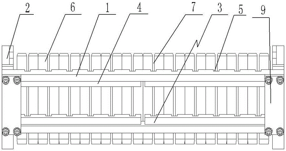
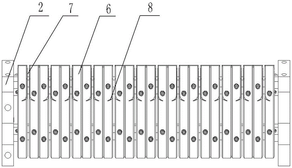

Image

  • Nail conveying device
  • Nail conveying device

Examples


Embodiment Construction

[0010] See figure 1 , figure 2 As shown, a nail feeding device includes two first horizontal plates 1 arranged in parallel. Two symmetrically arranged U-shaped mounting frames 3, the U-shaped mounting frame 3 includes a horizontal bar installed on the end support seat, and two second horizontal plates 4 close to the first horizontal plate 1, and the horizontal bar is fixed in the figure Below the plate 9, the lower ends of the first horizontal plate 1 and the second horizontal plate 4 respectively have a corresponding groove 5, and the two ends of each groove 5 are respectively provided with chute guide rails 6, between the two chute guide rails 6 A nail delivery gap 7 is left, and the chute guide rail 6 at one end is fixedly installed on the bottom of the first horizontal plate 1, and the chute guide rail 6 at the other end is fixedly installed on the bottom of the second horizontal plate 4; the width of the groove 5 is larger than that of the nail delivery gap 7 width, th...


PUM


Abstract

The invention relates to the technical field of wooden tray processing, in particular to a nail conveying device. By means of the nail conveying device, nail conveying can be achieved conveniently, rapidly and orderly. The nail conveying device comprises two first transverse plates which are arranged in parallel. The two ends of the first transverse plates are fixedly installed on an end supporting frame. Two U-shaped installation racks which are arranged symmetrically are arranged between the two first transverse plates. Each U-shaped installation rack comprises a transverse strip installed on end supporting seats and two second transverse plates abutting against the first transverse plates. Grooves are formed in the lower ends of the first transverse plates and the lower ends of the second transverse plates respectively in a one-to-one correspondence mode. Sliding groove guide rails are arranged at the two ends of each groove. A nail conveying gap is formed between every two adjacent slide groove guide rails, the slide groove guide rail at one end is fixedly installed at the bottoms of the first transverse plates, and the slide groove guide rail at the other end is fixedly installed at the bottoms of the second transverse plates.

Description

technical field [0001] The invention relates to the technical field of wood pallet processing, in particular to a nail feeding device. Background technique [0002] Wooden pallets are often used in production. They have the advantages of low price, easy processing, and strong practicability of finished products. Wooden pallets are generally made of multiple boards nailed together, and the nailing operation is very important for most small and medium-sized enterprises. Generally speaking, nailing is done manually, and the efficiency is very low. There are also pneumatic nails, but the common ones need to be transported manually one by one, and the efficiency is very low. Some also use feeding troughs for operation, but the structure is too simple, and the conveying effect is as good as The conveying efficiency is all unsatisfactory. Contents of the invention [0003] In order to solve the above problems, the present invention provides a nail feeding device, which can conve...

Claims


Application Information

Patent Timeline
IPC IPC(8): B27F7/13B65G35/00
CPCB27F7/13B65G35/00
Inventor 谢新华
Owner WUXI ZHENGYANG MACHINERY
Why Eureka
Eureka Blog
Learn More